Car anatomy / System by system

How a car
turns energy into motion.

Thousands of parts cooperate to do six jobs: store energy, create torque, deliver it to the road, control the car's motion, support the process, and protect the people inside.

Open the machine
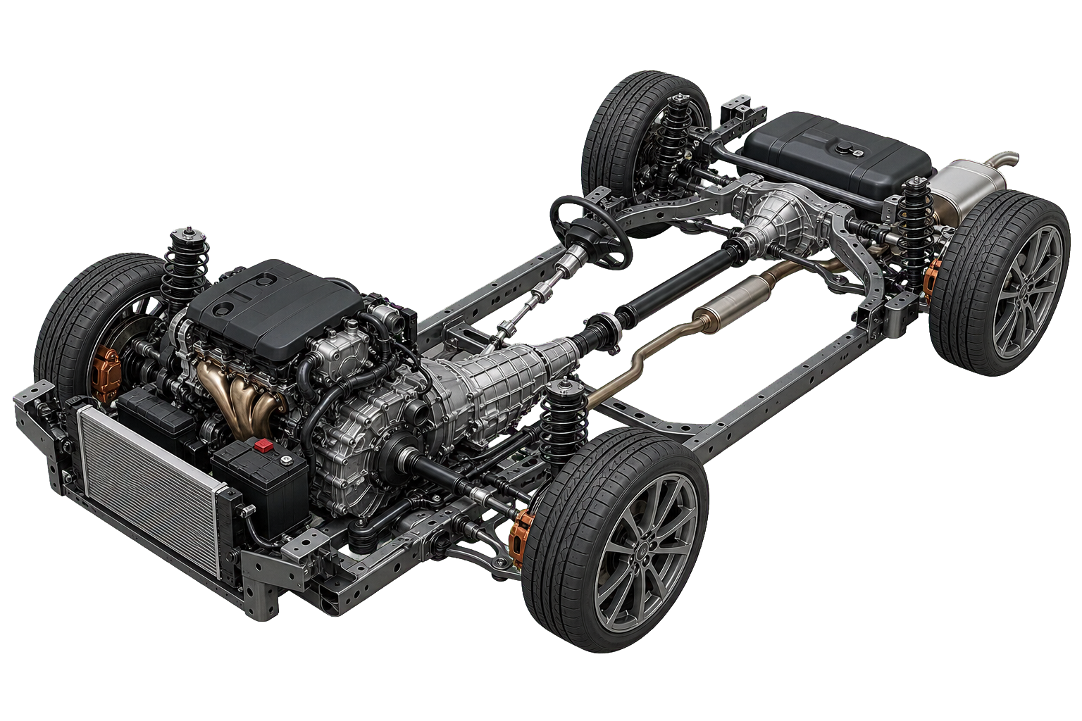
Passenger-car rolling chassis showing engine, transmission, driveline, suspension, steering, brakes, cooling system, fuel tank and wheels
Representative front-engine, all-wheel-drive layout · actual layouts vary
The governing idea

Every action is a chain

Pressing the accelerator does not directly turn a wheel. It asks a control system for torque. The engine or motor produces it; the driveline trades speed for force and divides that force between driven wheels; the tires finally push backward on the road so the road pushes the car forward. Steering, suspension, and brakes continuously shape what happens next.

INPUTStored energyChemical fuel or electrical charge
CONVERTRotating torqueCombustion engine or electric motor
TRANSMITWheel forceGears, differential, shafts and tires
RESULTVehicle motionAcceleration, cornering and braking
01–03 / Energy, power & driveline

Two routes to the same road

Combustion and electric cars store and convert energy differently. Downstream, both still need controlled torque at the tires.

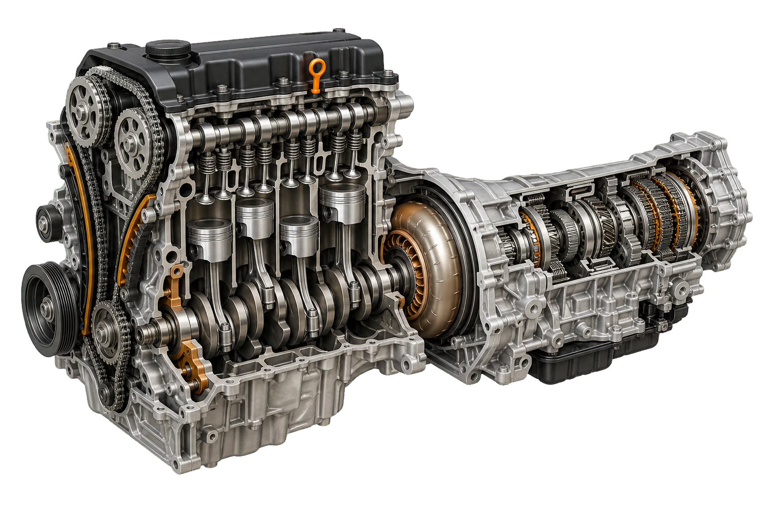
Cutaway combustion engine and automatic transmission showing pistons, crankshaft, valves, torque converter and gears
Combustion path

Pressure becomes rotation

Air and fuel burn inside each cylinder. Expanding gas pushes a piston; connecting rods turn the crankshaft; the crankshaft delivers a pulsing stream of torque.

  1. 01
    Intake & fuel system

    Measures incoming air and meters fuel so the engine can create a controlled mixture.

  2. 02
    Cylinders, pistons & valves

    Seal the combustion chambers, admit fresh charge, contain pressure, and expel exhaust.

  3. 03
    Crankshaft & flywheel

    Turn reciprocating piston motion into smoother rotation and carry it toward the gearbox.

  4. 04
    Transmission

    Selects a ratio: lower gears multiply wheel torque; higher gears reduce engine speed while cruising.
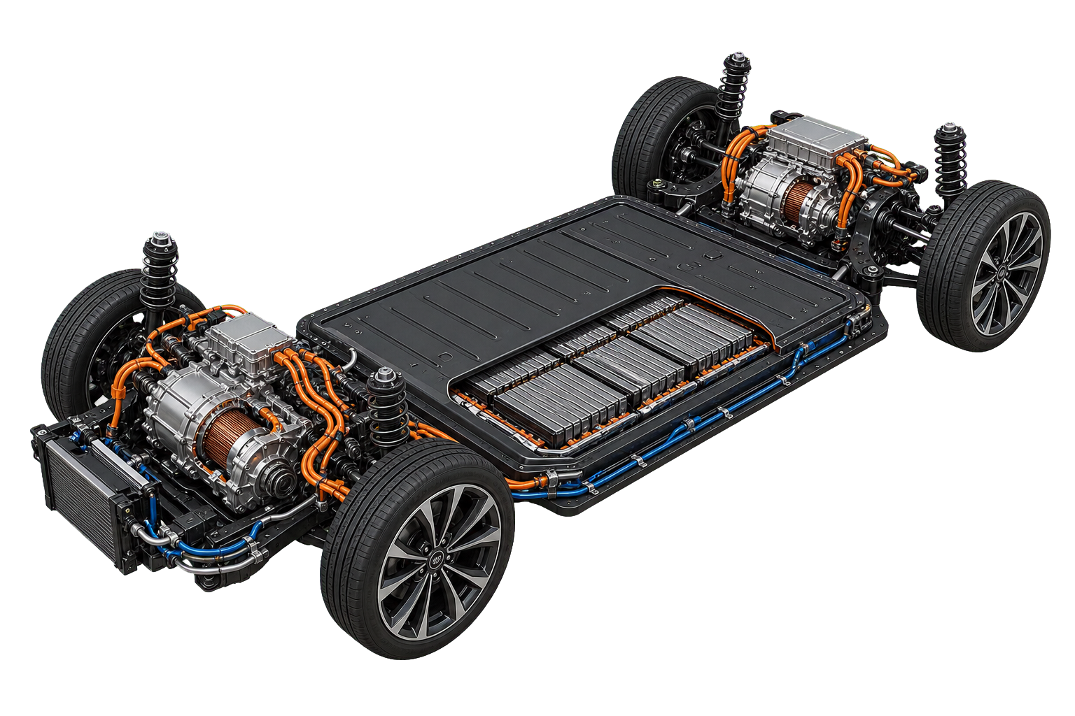
Electric-car skateboard powertrain showing the traction battery, cell modules, front and rear motors, inverters, cooling lines and high-voltage cables
Electric path

Current becomes a magnetic field

The battery supplies direct current. An inverter precisely switches that energy into alternating current, creating a rotating magnetic field in the motor that produces torque from zero speed.

  1. 01
    Traction battery & BMS

    Stores high-voltage energy while the battery-management system monitors cells, temperature, current, and safe limits.

  2. 02
    Inverter & motor

    Translate the accelerator request into controlled electrical phases and electromagnetic torque.

  3. 03
    Reduction gear

    Trades the motor's high rotational speed for greater torque at the wheels—usually with one fixed ratio.

  4. 04
    Regenerative braking

    Runs the motor as a generator during deceleration, returning some kinetic energy to the battery.

The shared path

From output shaft to tire contact patch

Clutch or torque converter
Connects a combustion engine to the transmission while allowing controlled slip during launch and shifts.
Driveshaft
Carries torque along the vehicle when the driven axle is separated from the power unit.
Differential
Apportions torque while allowing left and right wheels to rotate at different speeds in a turn.
Half-shafts & CV joints
Deliver torque to each driven wheel while suspension and steering change their angles.
Wheel & tire
The final mechanical interface. Its small contact patch must accelerate, brake, and corner the entire car.
04 / Vehicle dynamics

Point it, support it, stop it

The chassis systems do not merely keep the wheels attached. Together they manage tire load, wheel angle, body movement, road shocks, and the conversion of kinetic energy into heat.

01 Steering

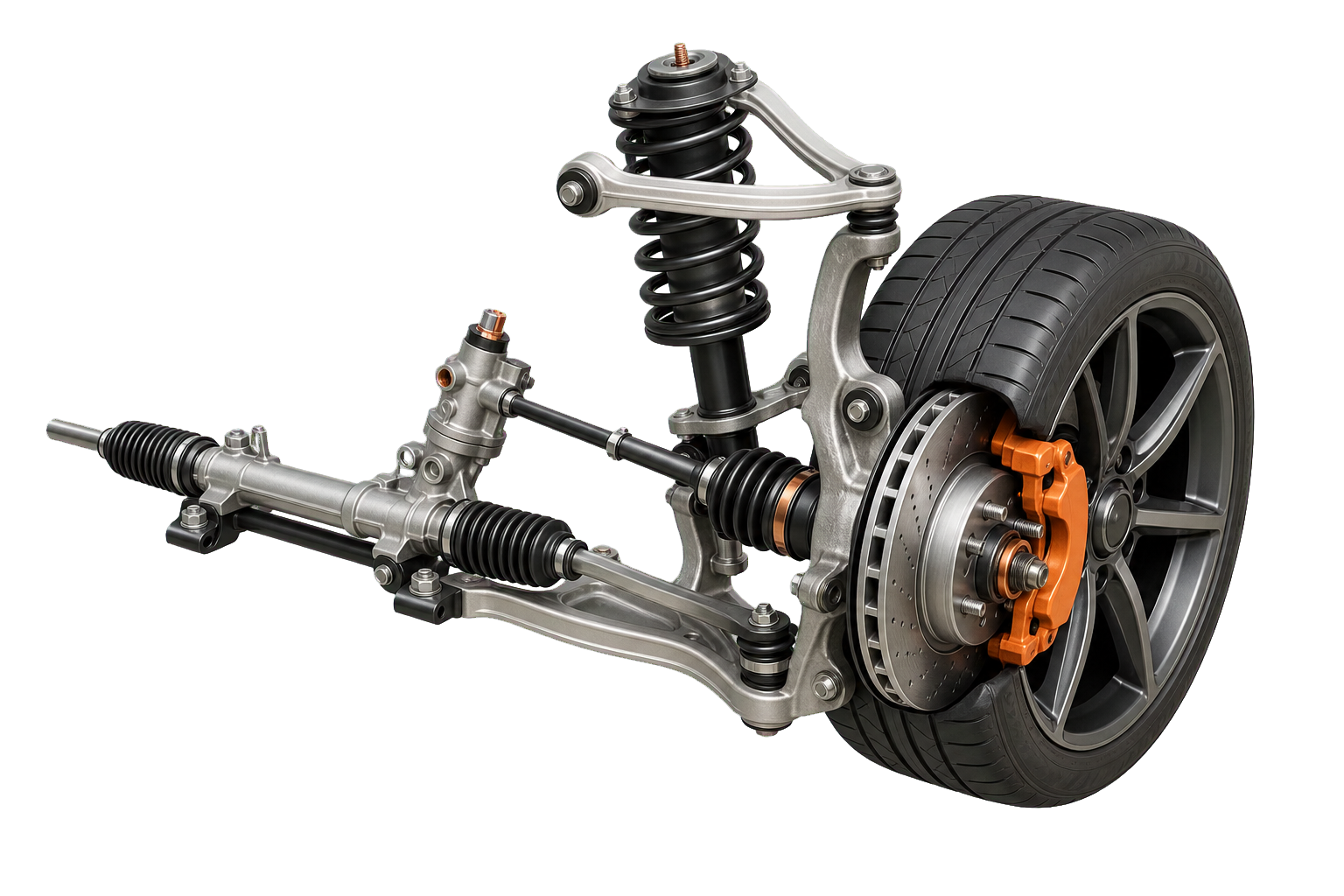
The steering wheel turns a pinion or actuator in the rack. Tie rods move the knuckles, changing each front wheel's angle. Power assistance reduces driver effort, not the need for mechanical control.

02 Suspension

Control arms locate the wheel; springs support the car's mass; dampers control oscillation; anti-roll bars resist excessive body roll by linking left and right suspension movement.

03 Brakes

Hydraulic pressure squeezes pads against rotating discs. Friction turns vehicle motion into heat. ABS rapidly modulates pressure to keep a tire near useful slip instead of fully locked.

04 Tires

Tread, carcass, rubber compound, pressure, temperature, and vertical load determine how much force the contact patch can generate. Every other dynamics system ultimately asks the tires to do the work.

Wheel-corner assembly with steering rack, tie rod, control arms, spring, damper, CV shaft, disc brake, caliper and tire
Representative independent front suspension · geometry varies by vehicle
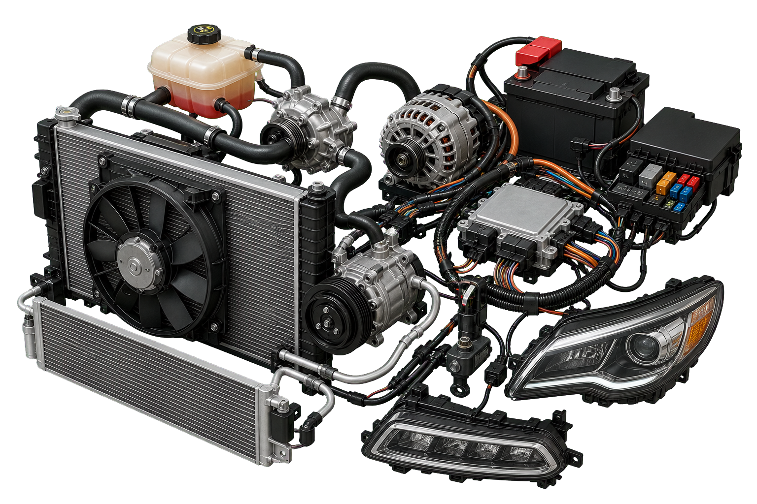
Automotive cooling and electrical components including radiator, fan, coolant reservoir, pumps, battery, alternator, ECU, fuse box, wiring and lights
05 / Support systems

The machinery behind the machinery

Power conversion creates heat and depends on precise control. These quieter systems make starting, temperature control, lighting, sensing, and cabin comfort possible.

THERMALCooling circuit

Pump, passages, thermostat, radiator and fan move heat from the engine, motor, inverter or battery into outside air.

LOW VOLTAGE12-volt electrical system

Powers computers, lights, locks, pumps and safety controllers. An alternator or DC–DC converter replenishes it.

CONTROLECUs, sensors & networks

Measure conditions, exchange messages and command actuators—from fuel injectors to brake valves and cooling fans.

CLIMATEHeating, ventilation & A/C

Moves and conditions cabin air. A refrigerant circuit transports heat; a heater core or electric heater supplies warmth.

BREATHINGIntake & exhaust

Filters and meters incoming air, then routes exhaust through emissions controls and silencers in combustion vehicles.

LUBRICATIONOil circuits

Reduce friction, carry heat and protect loaded surfaces in engines, gearboxes, differentials and drive units.

The low-voltage power loop

Battery starts it. Alternator sustains it.

In a combustion car, the 12-volt battery supplies the short burst needed to crank the engine. Once running, the engine spins the alternator, which powers the electrical bus and restores the battery's charge. Electric cars replace the alternator with a DC–DC converter fed by the traction battery.

06 / Structure & safety

Control the crash pulse

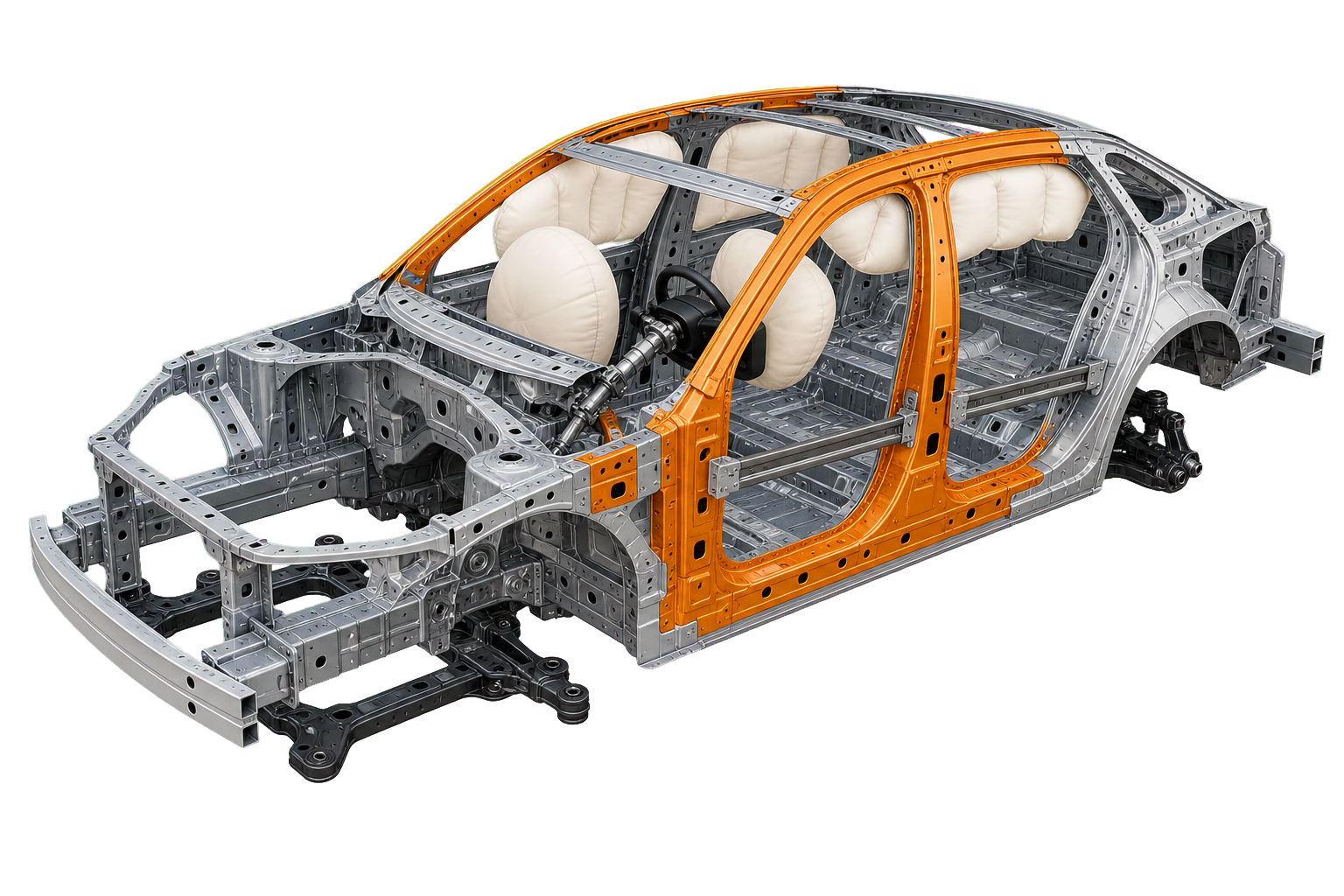
A safe structure is not simply rigid. Front and rear zones deform to absorb energy over time, while the passenger cell resists intrusion. Restraints then manage how occupants decelerate inside that protected space.

  1. 01
    Detect

    Accelerometers and pressure sensors identify a severe impact in milliseconds.

  2. 02
    Deform

    Crumple zones fold along engineered paths, extending the stopping time and redirecting loads.

  3. 03
    Restrain

    Seat-belt pretensioners remove slack; load limiters manage belt force across the torso.

  4. 04
    Cushion

    Airbags create supplementary surfaces that spread load and reduce contact with hard structures.

  5. 05
    Isolate

    Fuel or high-voltage systems shut down where possible, while doors and the safety cell preserve an exit space.

Passenger-car body-in-white showing safety cell, crumple zones, reinforced pillars, side-impact beams, subframes, steering column and deployed airbags
Component index

The major parts, at a glance

Names describe functions; packaging and construction vary across eras and vehicles.

Power source

Fuel tank · fuel pump · intake · engine · exhaust · traction battery · battery-management system · inverter · motor

Torque path

Clutch · torque converter · transmission · reduction gear · transfer case · driveshaft · differential · half-shafts · CV joints

Running gear

Subframes · control arms · springs · dampers · anti-roll bars · steering rack · knuckles · hubs · wheels · tires

Braking

Pedal and booster · master cylinder · hydraulic lines · ABS unit · calipers · pads · discs or drums · parking brake

Support

Radiator · pumps · thermostat · fans · lubricating circuits · 12-volt battery · alternator or DC–DC converter · ECUs · wiring

Body & safety

Unibody or frame · crumple zones · safety cell · doors and glazing · seats · belts · pretensioners · airbags · impact sensors

Complete component atlas

167 major parts, documented

Search by name, synonym, purpose, location, or operating principle. Use the system filters to narrow the machine. Electrical and control is fully illustrated, and the combustion-engine collection is now underway with individual transparent component renders.

167parts shown
Vehicle type
01

Electrical & control

19 parts · 19 illustrated
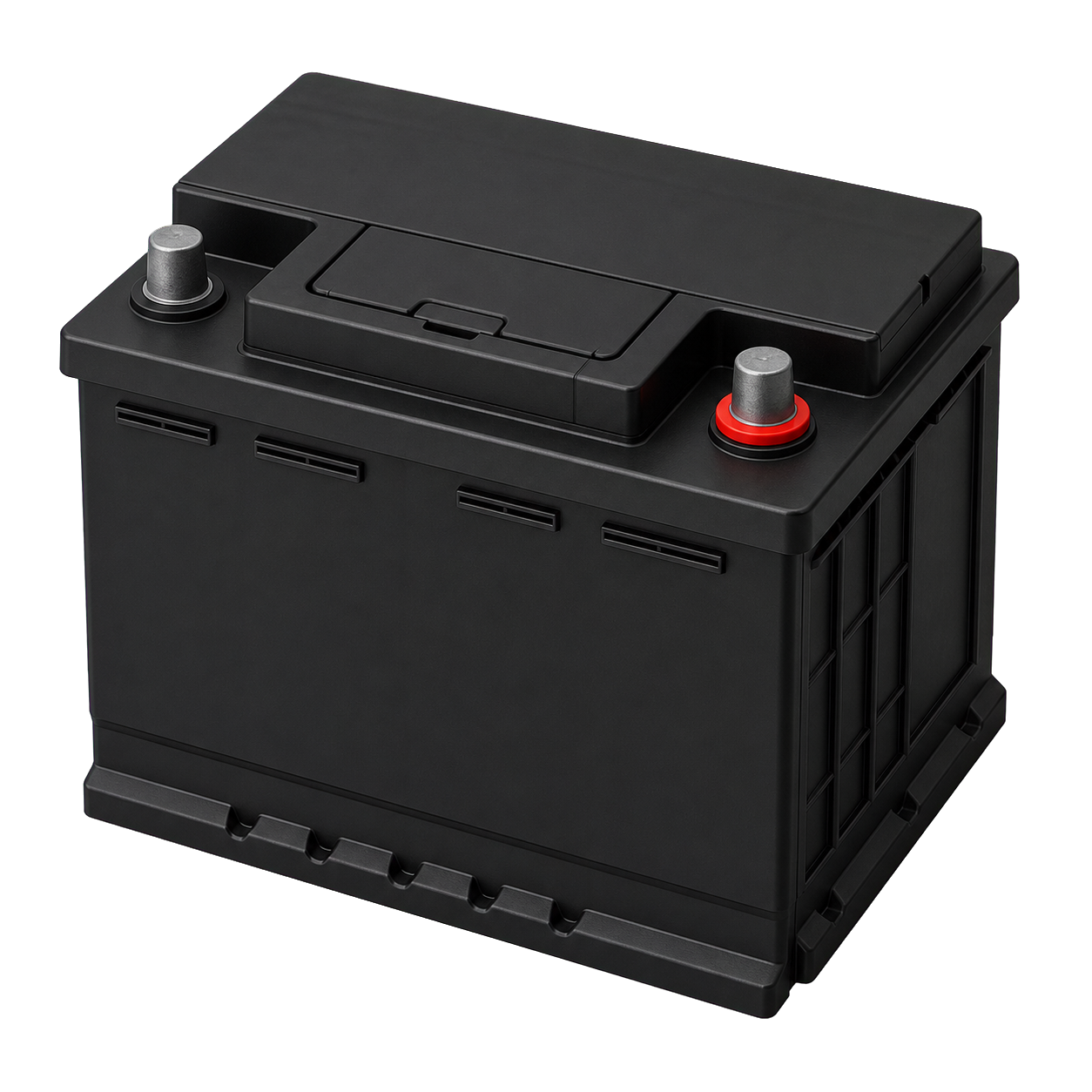
Technical illustration of 12-volt battery
All 12-volt battery starter battery, auxiliary battery

Stores low-voltage energy for starting, computers, locks, lighting, and safety systems.

Location
Usually in the engine bay, trunk, or beneath a seat
How it works
Lead-acid or lithium cells create direct current chemically. An alternator or DC–DC converter recharges it while the car operates.
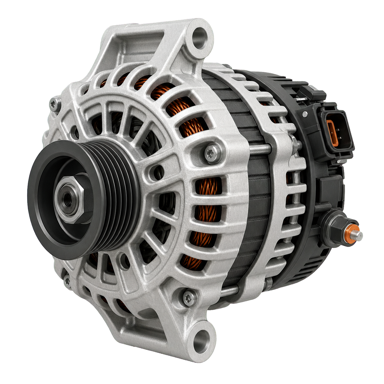
Technical illustration of Alternator
Combustion Alternator generator

Supplies electrical power and recharges the 12-volt battery while the engine runs.

Location
Belt-driven at the front or side of the engine
How it works
A rotating magnetic field induces alternating current in stator windings; rectifier diodes convert it to direct current and a regulator controls voltage.
Technical illustration of Starter motor
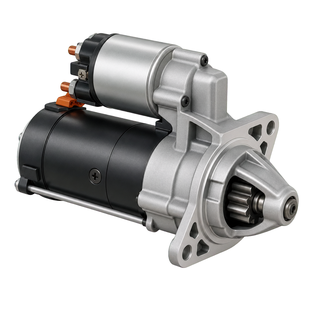
Combustion Starter motor

Cranks the engine fast enough for combustion to begin.

Location
Bolted where the engine meets the transmission
How it works
High current from the battery spins a powerful DC motor whose pinion temporarily engages the flywheel or flexplate ring gear.
Technical illustration of Starter solenoid
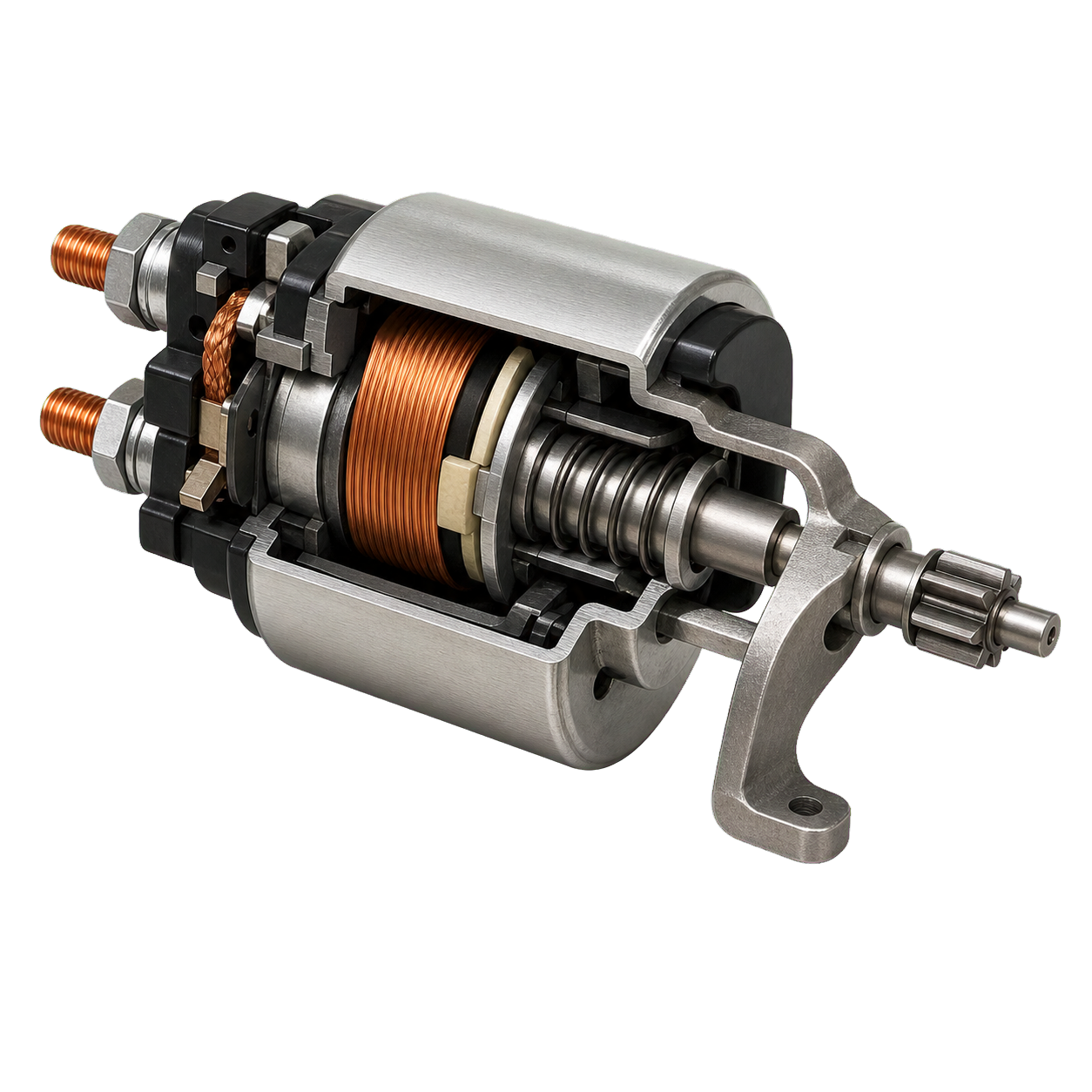
Combustion Starter solenoid

Switches starter current and moves the starter pinion into engagement.

Location
Mounted on or near the starter motor
How it works
An electromagnetic coil pulls a plunger that closes heavy electrical contacts and shifts the drive gear.
Technical illustration of Fuse
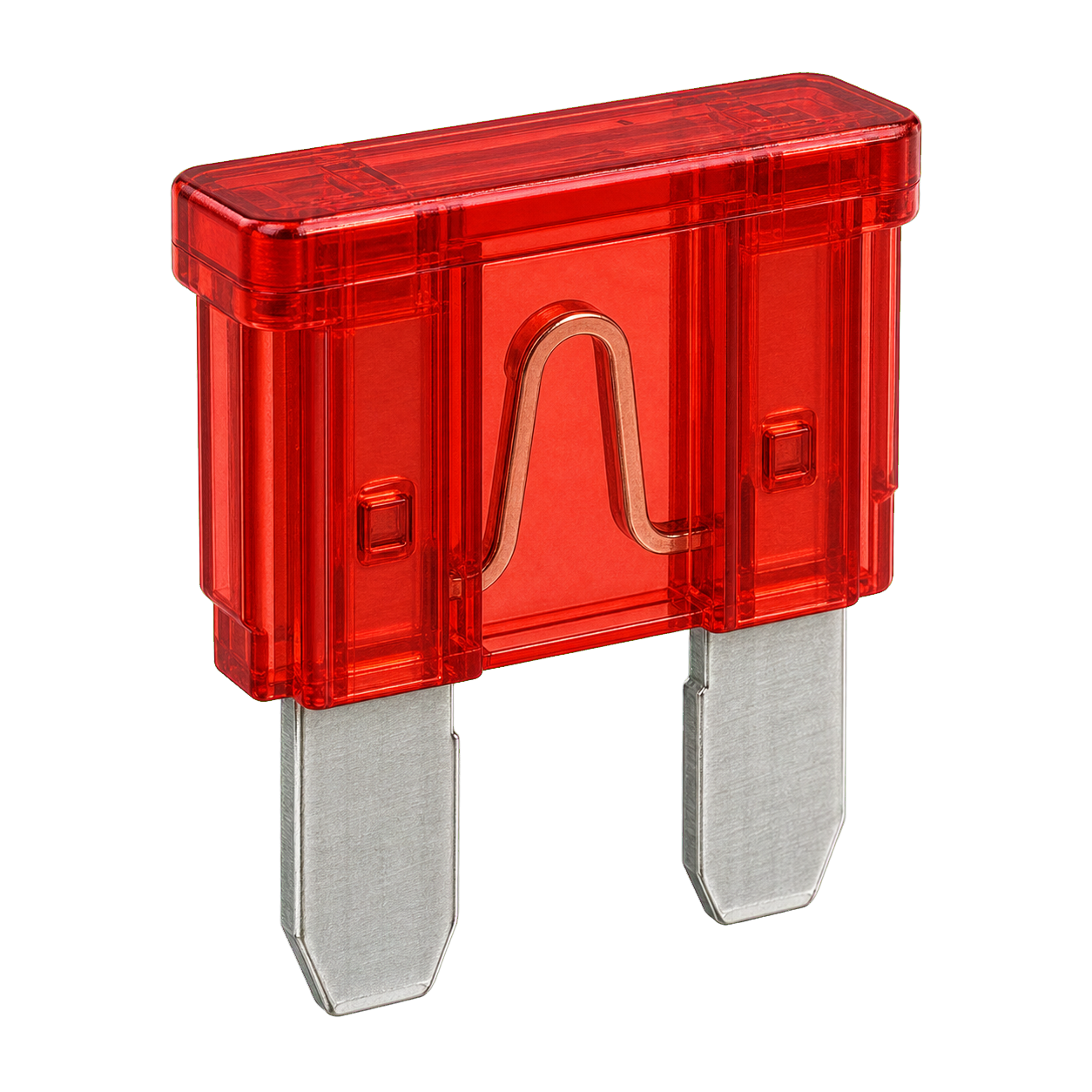
All Fuse

Protects wiring and devices from excessive current.

Location
Fuse boxes in the cabin, engine bay, trunk, and high-voltage battery
How it works
A calibrated metal element melts and opens the circuit when current remains above its safe rating.
Technical illustration of Relay
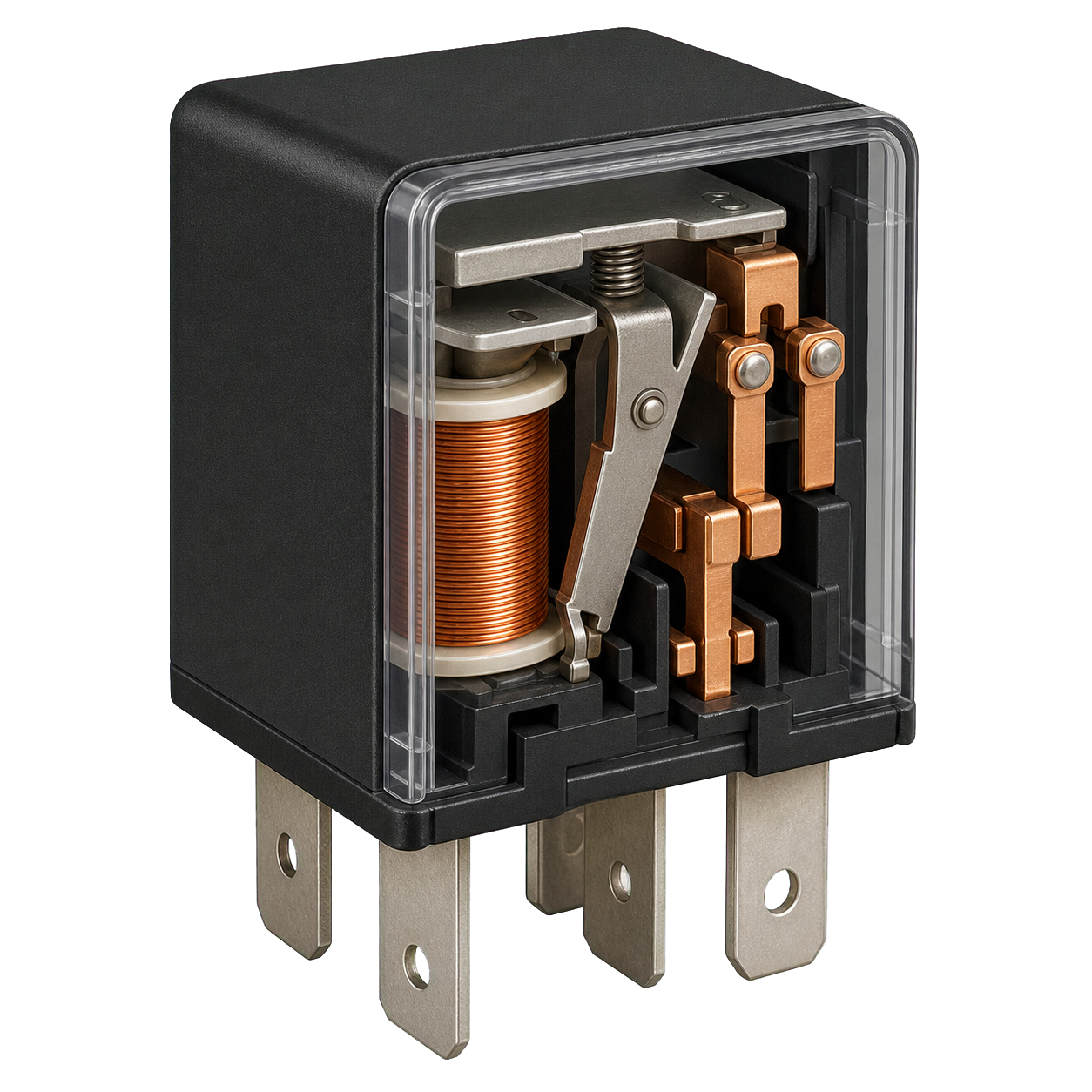
All Relay

Lets a low-current control signal switch a higher-current load.

Location
Fuse and relay boxes or integrated power modules
How it works
An electromagnet moves contacts; solid-state relays perform the same function electronically.
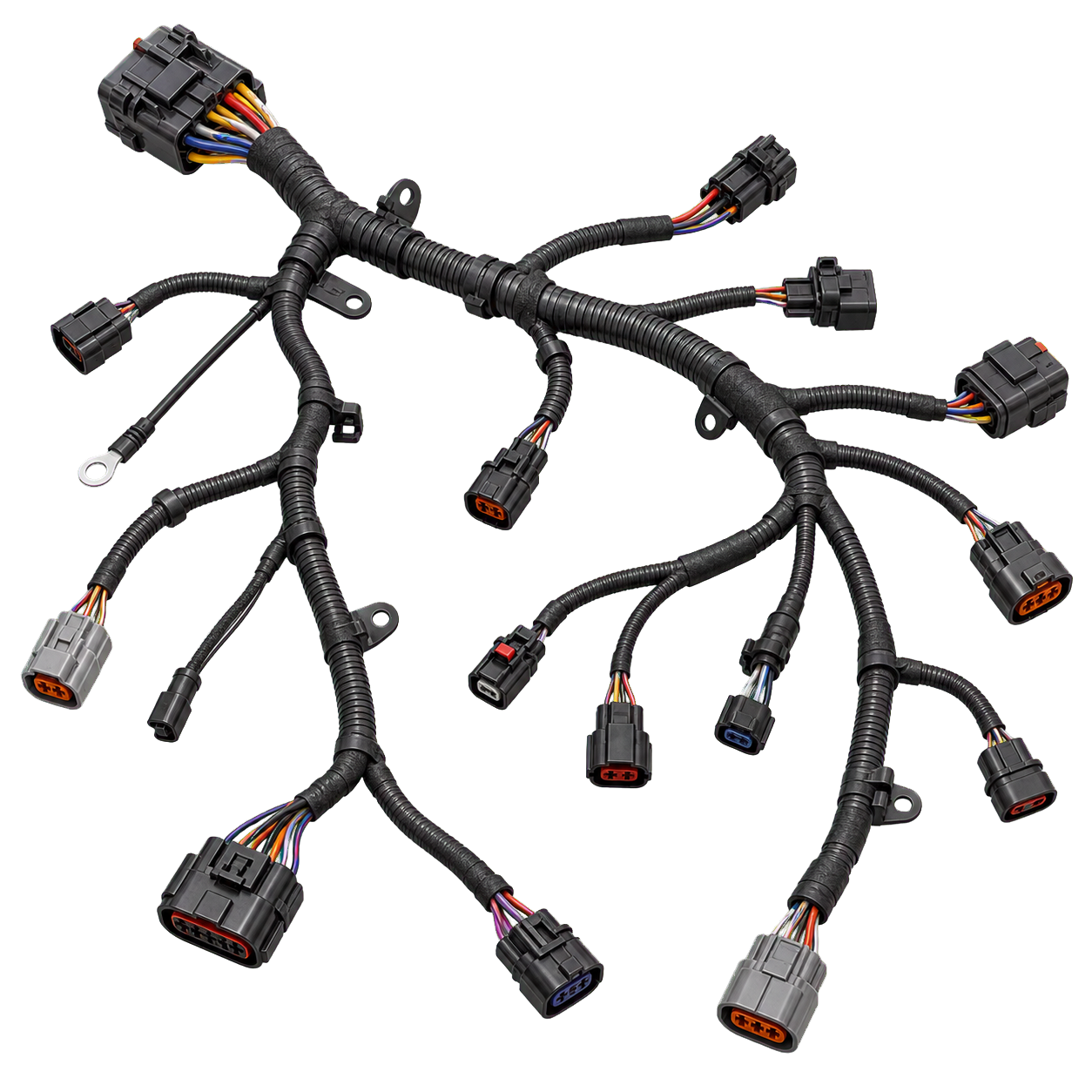
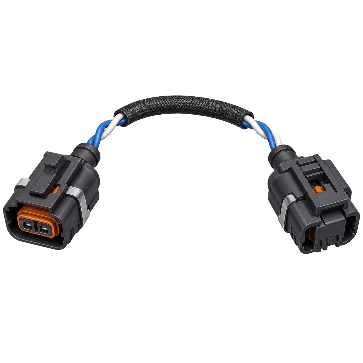
Technical illustration of Wiring harness
All Wiring harness

Distributes power and communication signals between components.

Location
Routed throughout the body, chassis, engine bay, and doors
How it works
Bundled conductors, connectors, shielding, and protective sleeves create the car's electrical nervous system.
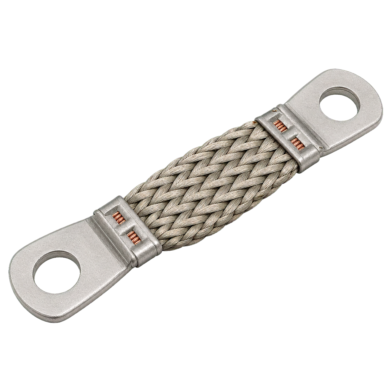
Technical illustration of Ground strap
All Ground strap earth strap

Provides a low-resistance return path for electrical current.

Location
Between battery, body, engine, transmission, and chassis
How it works
Braided or heavy-gauge conductors bond major structures to the battery's negative terminal.
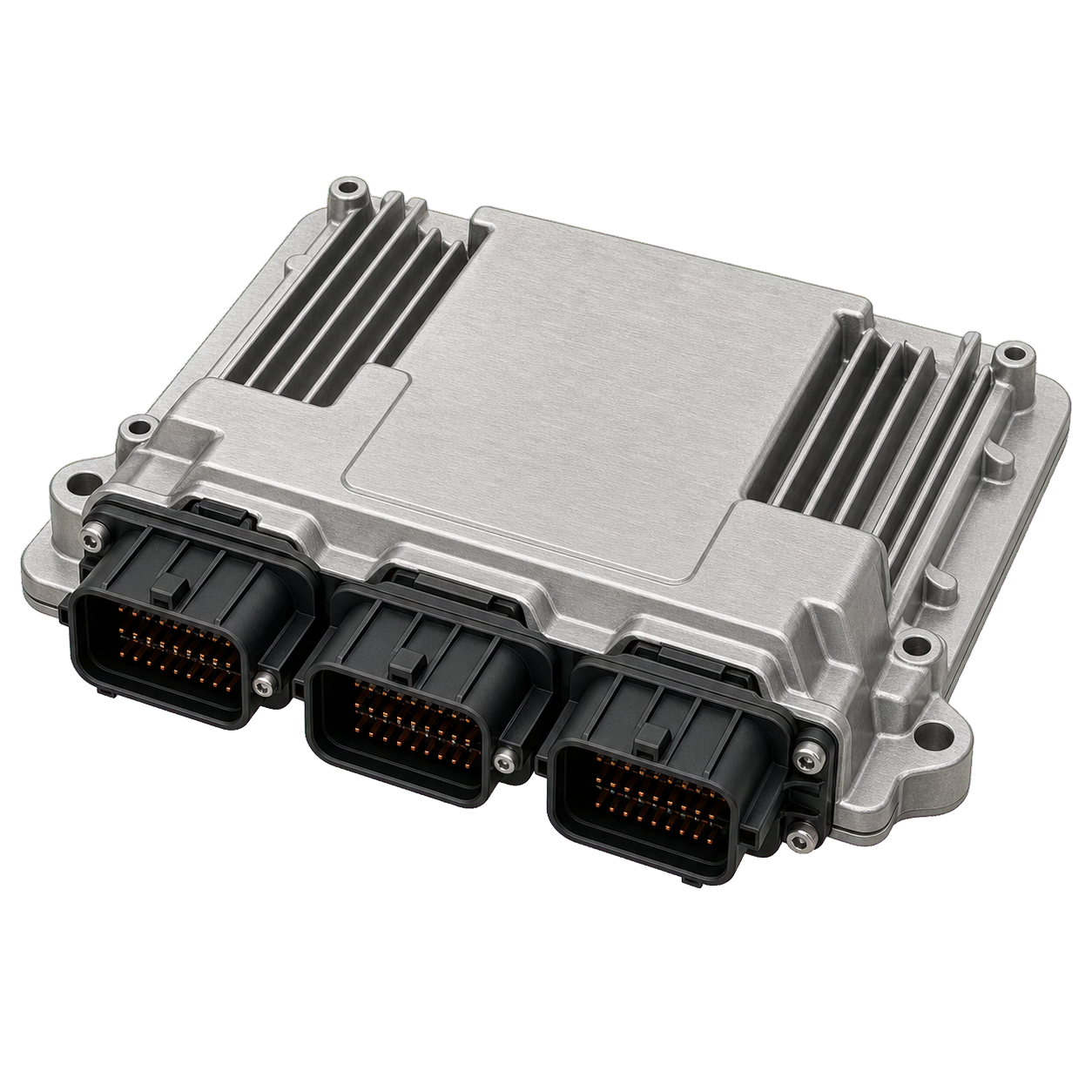
Technical illustration of Engine control unit
Combustion Engine control unit ECU, ECM

Controls fuel, ignition, throttle, emissions equipment, and engine protection.

Location
Protected area of the engine bay or cabin
How it works
A real-time computer reads sensors, applies calibrated maps and control loops, then commands injectors, coils, valves, and actuators.
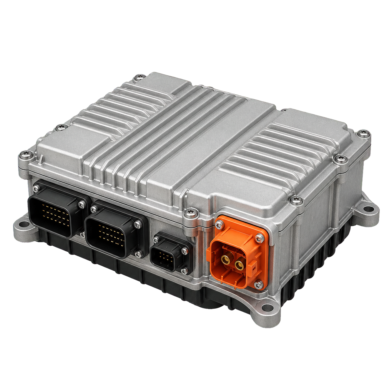
Technical illustration of Vehicle control unit
Electric Vehicle control unit VCU

Coordinates torque, charging, braking, thermal management, and high-voltage safety.

Location
Protected electronics enclosure
How it works
It interprets driver requests and vehicle states, then arbitrates commands among the inverter, battery, brakes, and other controllers.
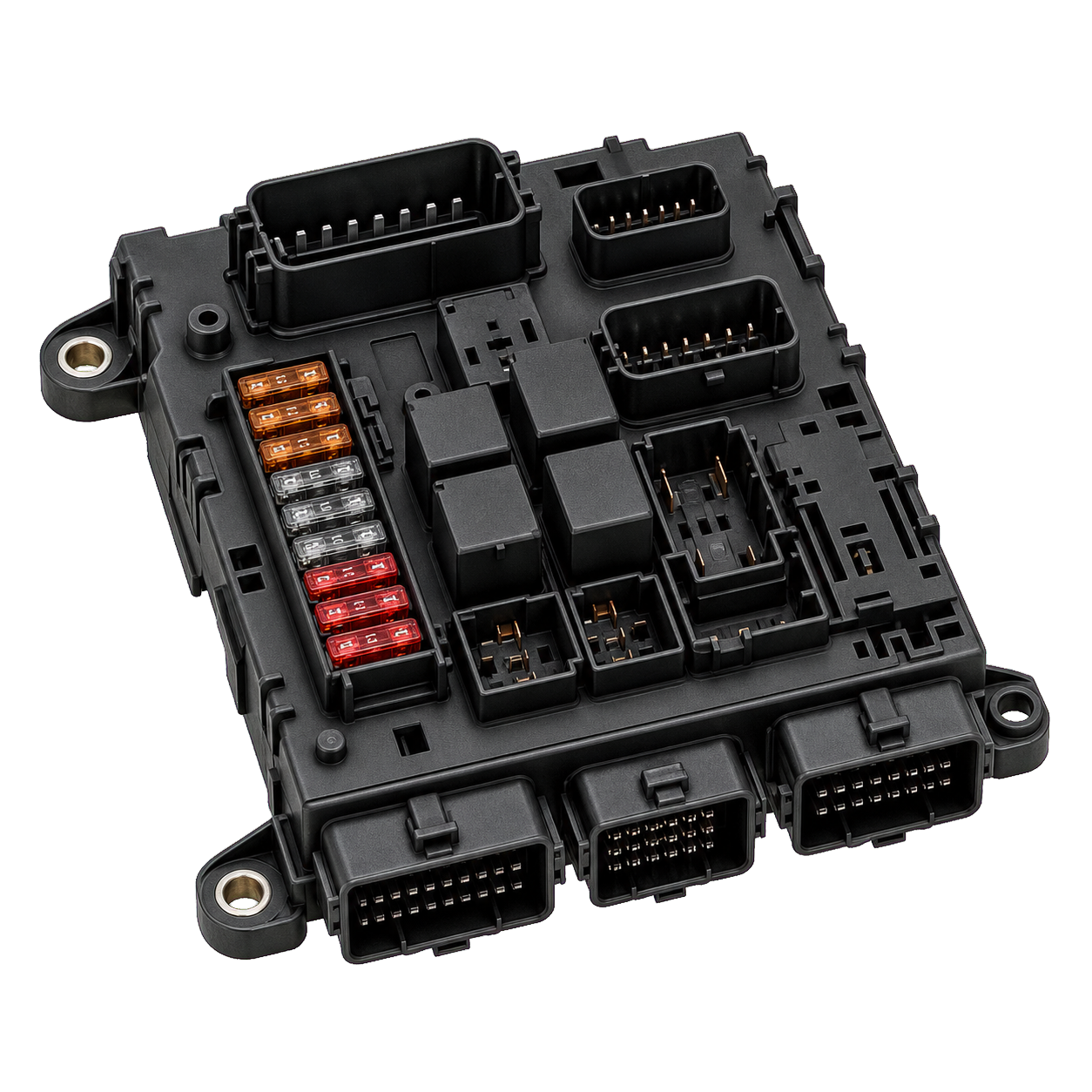
Technical illustration of Body control module
All Body control module BCM

Coordinates lights, locks, windows, wipers, alarms, and other body functions.

Location
Usually behind the dashboard or in a cabin fuse box
How it works
It receives switch and network messages and controls distributed relays or electronic outputs.
Technical illustration of CAN bus
All CAN bus vehicle network

Allows control units to exchange data without dedicated wires for every signal.

Location
Twisted-pair wiring linking electronic modules
How it works
Modules broadcast prioritized digital messages over shared differential communication lines.
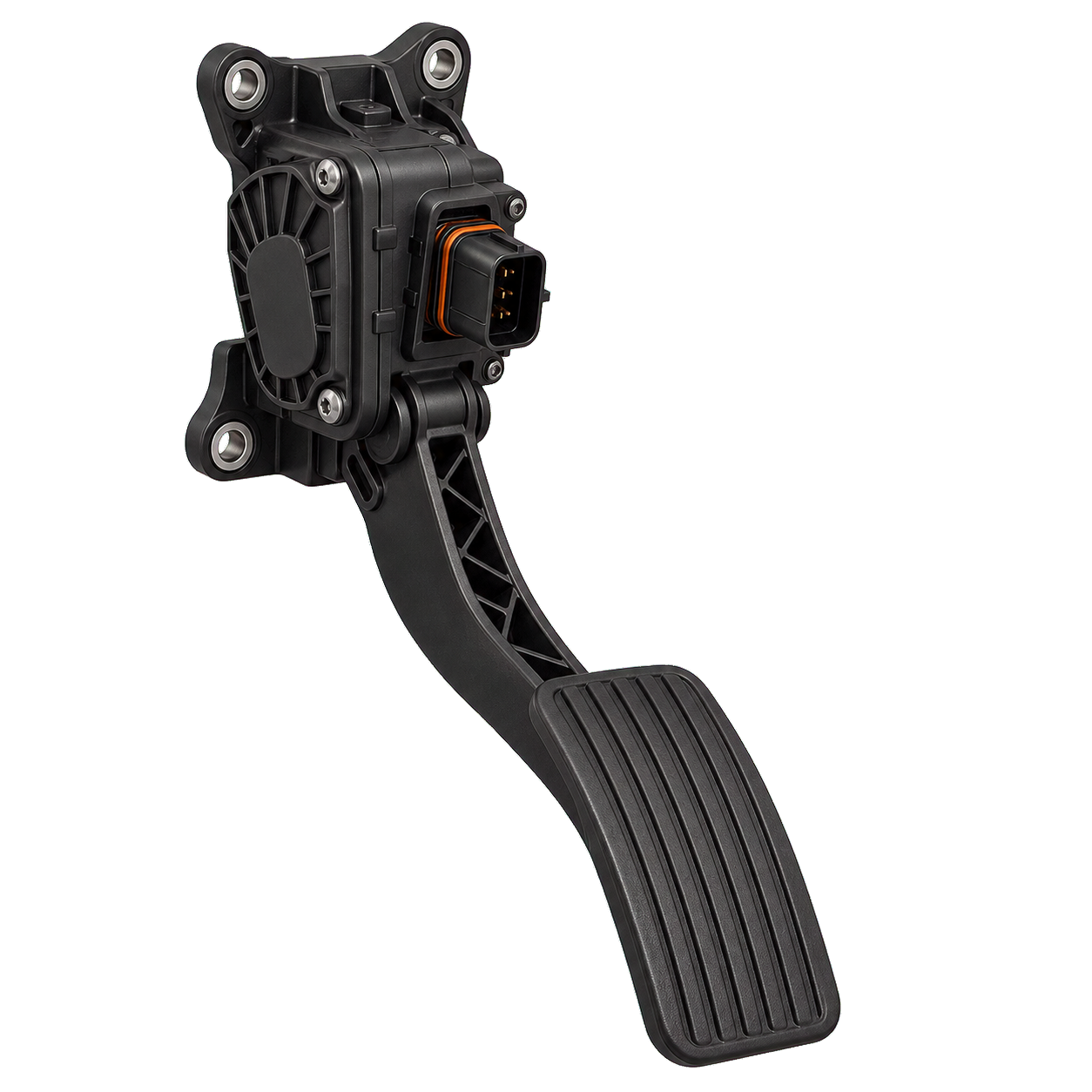
Technical illustration of Accelerator-pedal sensor
All Accelerator-pedal sensor APP sensor

Reports the driver's torque request.

Location
Integrated with the accelerator pedal
How it works
Redundant position sensors convert pedal travel into electrical signals checked for agreement by the control system.
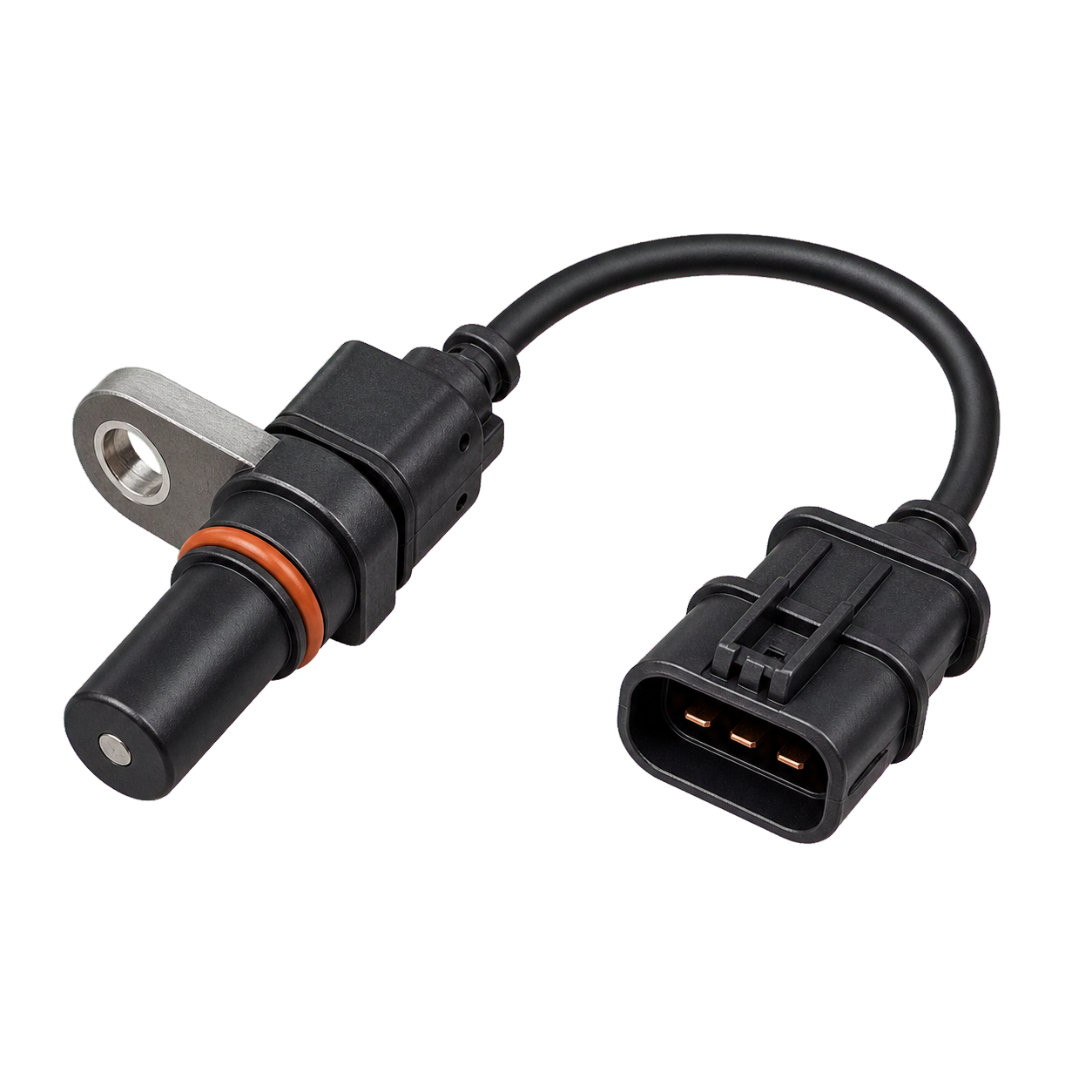
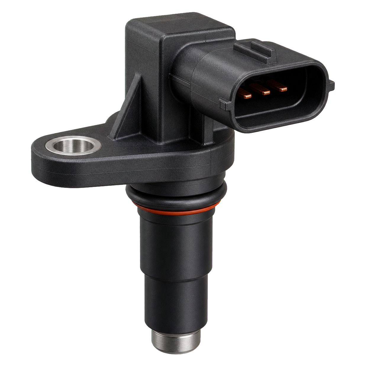
Technical illustration of Crankshaft-position sensor
Combustion Crankshaft-position sensor

Tells the ECU engine speed and exact crank position.

Location
Near the crankshaft pulley, flywheel, or engine block
How it works
A magnetic or Hall-effect sensor reads teeth on a rotating trigger wheel so ignition and injection can be timed.
Technical illustration of Camshaft-position sensor
Combustion Camshaft-position sensor

Identifies valve-cycle phase and supports variable valve timing.

Location
Cylinder head near a camshaft trigger wheel
How it works
A Hall-effect or magnetic sensor detects a patterned target attached to the camshaft.
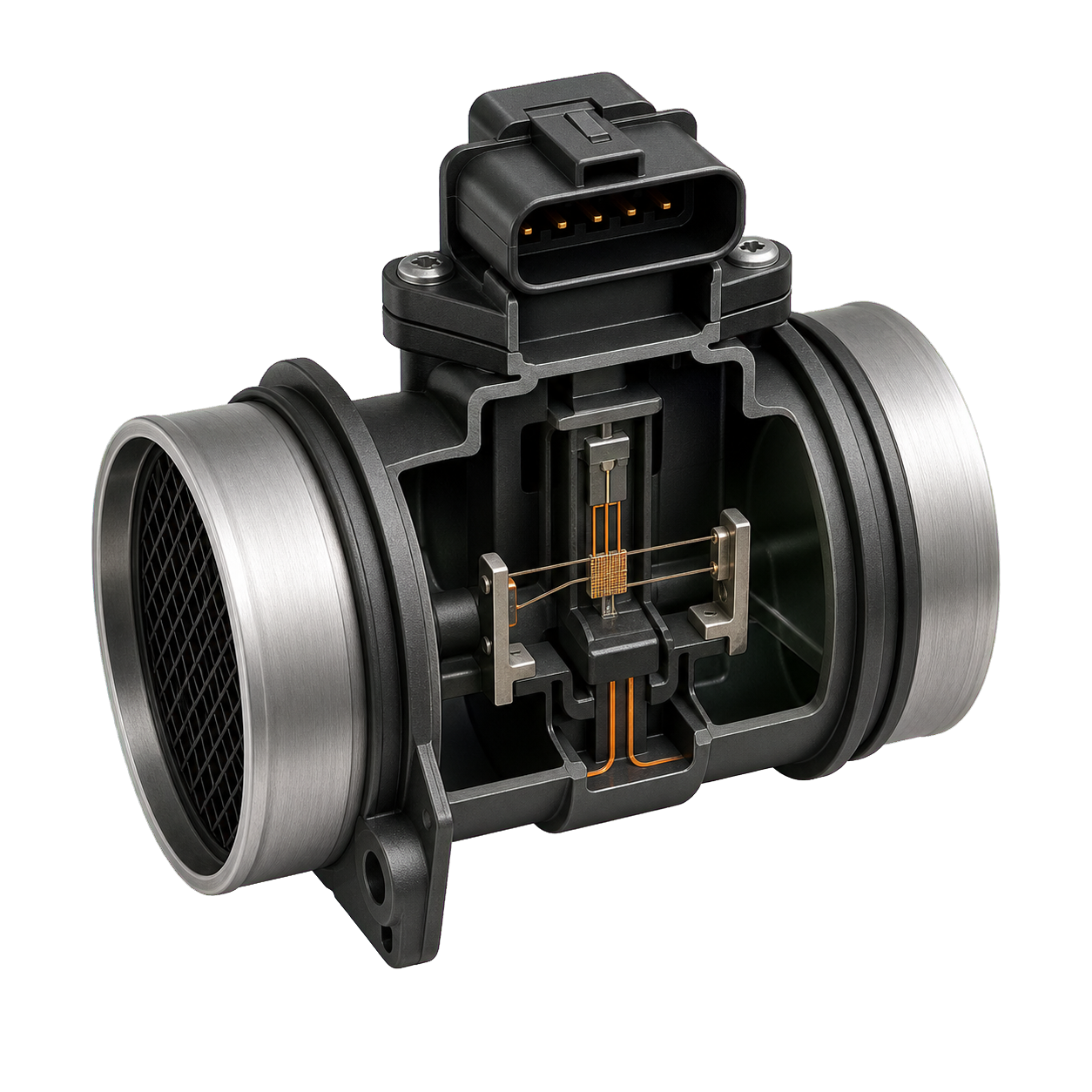
Technical illustration of Mass-airflow sensor
Combustion Mass-airflow sensor MAF

Measures the mass of air entering the engine.

Location
Intake duct after the air filter
How it works
A heated element is cooled by airflow; the current required to maintain its temperature indicates air mass.
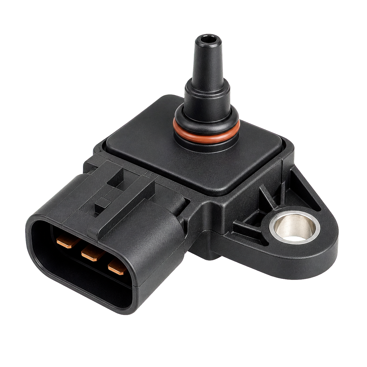
Technical illustration of Manifold-pressure sensor
Combustion Manifold-pressure sensor MAP sensor

Measures intake pressure for load, fueling, and boost calculations.

Location
On or connected to the intake manifold
How it works
A pressure-sensitive electronic element converts manifold pressure into a voltage or digital signal.
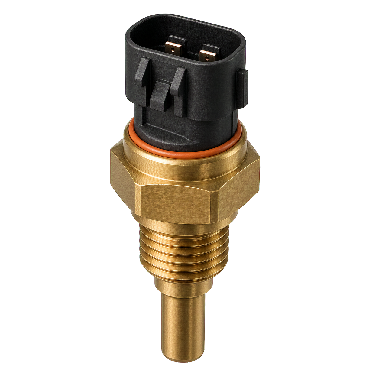
Technical illustration of Temperature sensors
All Temperature sensors

Let controllers protect components and regulate performance or comfort.

Location
Coolant, oil, intake, cabin, battery, motor, and ambient locations
How it works
Thermistors change resistance with temperature; controllers convert that change into a calibrated reading.
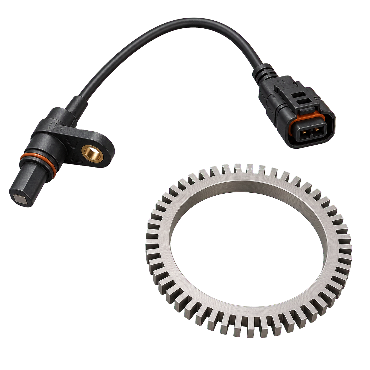
Technical illustration of Wheel-speed sensor
All Wheel-speed sensor

Reports individual wheel speed to ABS, stability control, traction control, and driver-assistance systems.

Location
At each wheel hub or bearing
How it works
A magnetic encoder and Hall-effect sensor generate pulses as the wheel rotates.
02

Combustion engine

20 parts · 6 illustrated
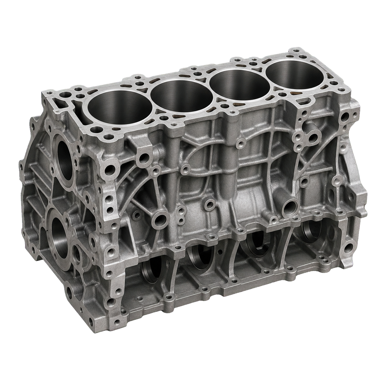
Technical illustration of Engine block
Combustion Engine block cylinder block

Houses cylinders, crankshaft supports, oil passages, and coolant jackets.

Location
Core lower structure of the engine
How it works
A rigid cast structure contains combustion loads and aligns the engine's rotating assembly.
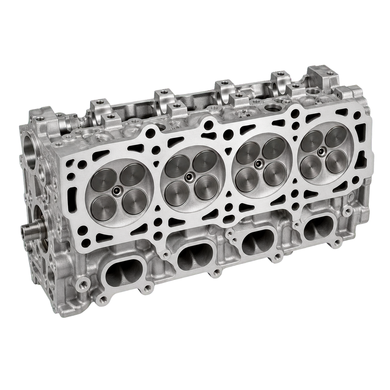
Technical illustration of Cylinder head
Combustion Cylinder head

Forms the combustion-chamber roof and carries valves, ports, spark plugs or injectors.

Location
Bolted to the top of the engine block
How it works
Passages route intake, exhaust, coolant, and oil while the valvetrain controls gas exchange.
Combustion Head gasket

Seals combustion pressure while separating oil and coolant passages.

Location
Clamped between block and cylinder head
How it works
A multilayer metal or composite gasket conforms under bolt load to microscopic surface irregularities.
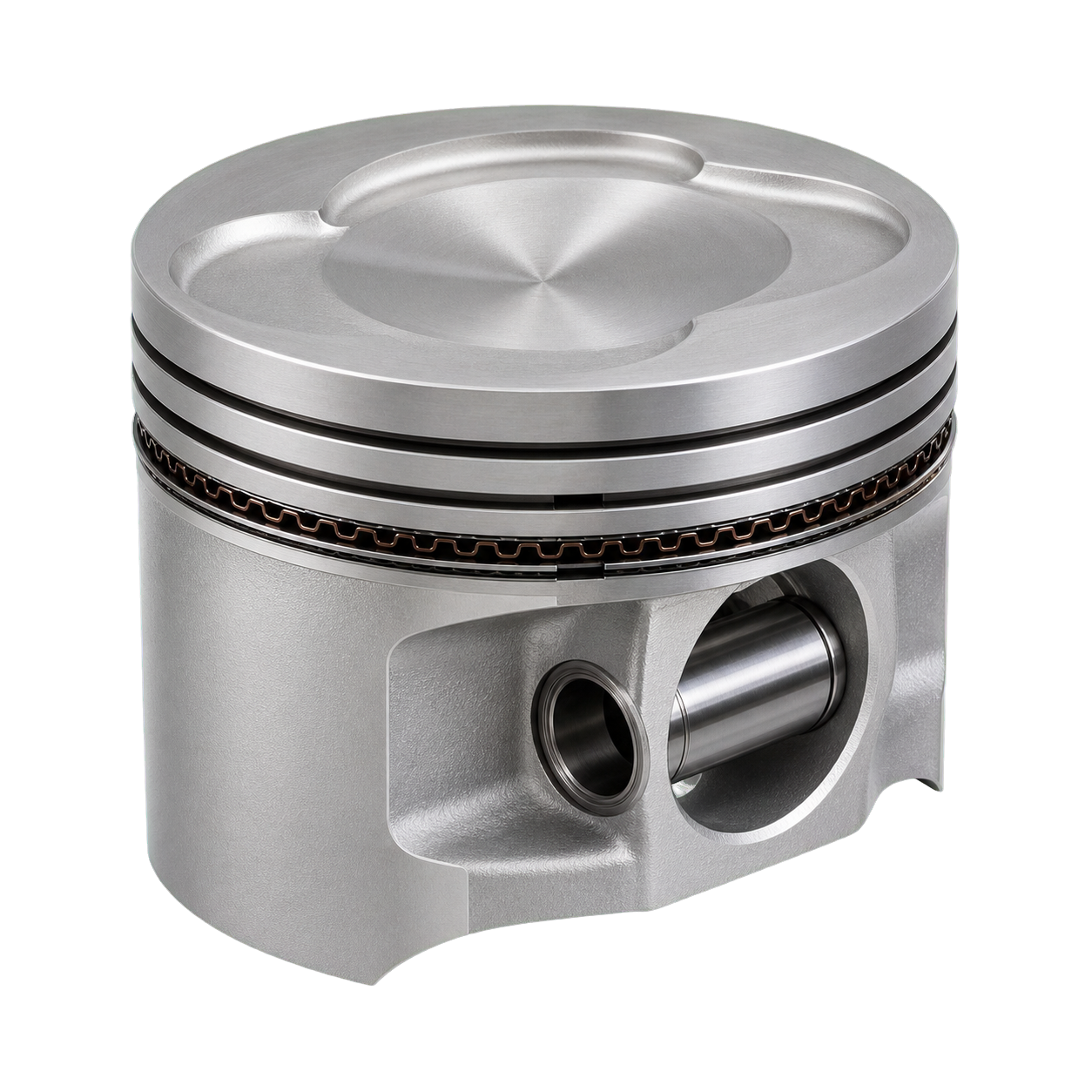
Technical illustration of Piston
Combustion Piston

Receives combustion pressure and transfers force to the connecting rod.

Location
Reciprocates inside each cylinder
How it works
The piston slides in the bore through four strokes while its crown contains heat and pressure.
Combustion Piston rings

Seal combustion, control oil on the cylinder wall, and conduct heat into the block.

Location
Grooves around each piston
How it works
Springy split rings press outward against the cylinder bore while moving with the piston.
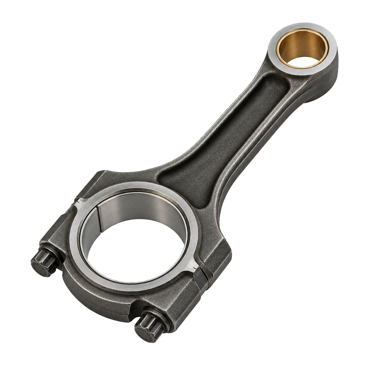
Technical illustration of Connecting rod
Combustion Connecting rod

Transfers piston force to the crankshaft.

Location
Between each piston and the crankshaft
How it works
Its small end pivots on the wrist pin while the big end orbits a crank journal.
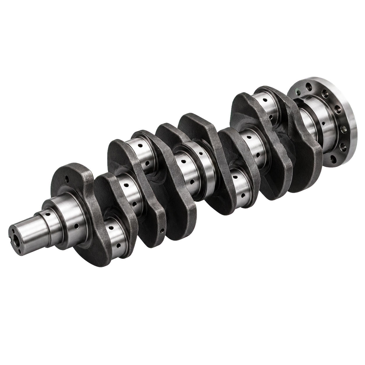
Technical illustration of Crankshaft
Combustion Crankshaft

Converts reciprocating piston motion into rotary torque.

Location
Main bearings in the lower engine block
How it works
Offset crank throws receive force from connecting rods while counterweights balance the assembly.
Combustion Main and rod bearings

Support the crankshaft on a thin pressurized oil film.

Location
Between crankshaft journals, block, and connecting rods
How it works
Replaceable bearing shells maintain clearance so hydrodynamic oil pressure prevents metal-to-metal contact.
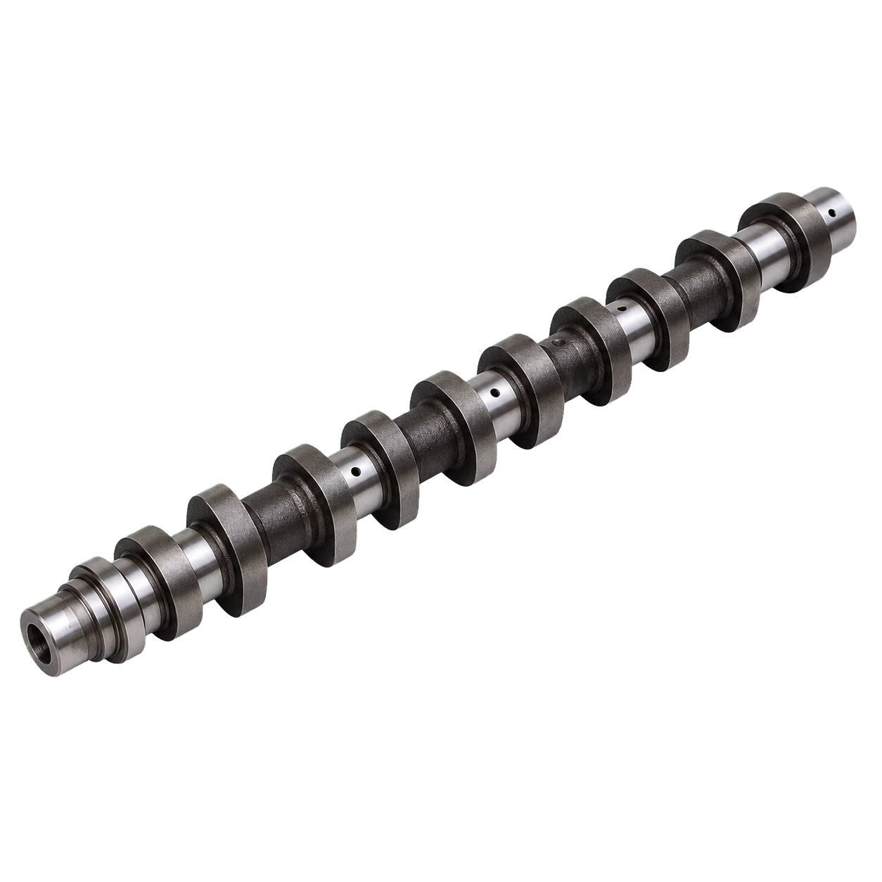
Technical illustration of Camshaft
Combustion Camshaft

Opens intake and exhaust valves at the required time and lift.

Location
Cylinder head or engine block
How it works
Eccentric lobes rotate at half crankshaft speed in a four-stroke engine and act through followers or rocker arms.
Combustion Intake and exhaust valves

Control gases entering and leaving each cylinder.

Location
Cylinder-head ports
How it works
Cam-driven stems lift the valve heads from their seats; springs close them and restore the seal.
Combustion Valve springs

Close valves and keep the valvetrain following the cam profile.

Location
Around valve stems in the cylinder head
How it works
Compressed coil springs store energy as valves open and return them to their seats.
Combustion Rocker arm or cam follower

Transfers and sometimes multiplies camshaft motion to the valves.

Location
Between cam lobes and valves
How it works
A pivoting arm or sliding/rolling follower tracks the cam lobe and pushes the valve stem.
Combustion Timing belt or chain

Synchronizes camshaft and crankshaft rotation.

Location
Front or rear of the engine behind covers
How it works
A toothed belt or metal chain links sprockets in a fixed phase, controlled by guides and tensioners.
Combustion Variable-valve-timing actuator cam phaser

Changes valve timing to improve torque, efficiency, emissions, or power.

Location
Camshaft sprocket or valvetrain
How it works
Oil pressure or an electric actuator rotates the cam relative to its drive sprocket under ECU control.
Combustion Flywheel or flexplate

Smooths engine pulses and connects the engine to a clutch or torque converter.

Location
Rear of the crankshaft
How it works
Rotational inertia carries the crankshaft between firing events; a ring gear also engages the starter.
Most Engine mount

Supports the powertrain while isolating vibration and limiting movement.

Location
Between powertrain and body or subframe
How it works
Rubber, hydraulic, or electronically controlled mounts deform to absorb selected frequencies and loads.
Combustion Oil pump

Circulates pressurized oil to bearings, valvetrain, turbocharger, and actuators.

Location
Inside the engine, driven by crankshaft, chain, or gear
How it works
Gear, gerotor, or variable-displacement elements draw oil from the sump and force it through galleries.
Combustion Oil pan sump

Stores returning engine oil and encloses the crankcase.

Location
Bottom of the engine
How it works
Oil drains into the pan, where a pickup feeds it back to the pump.
Combustion Oil filter

Removes wear particles and contaminants from circulating oil.

Location
On the engine block or in a remote housing
How it works
Oil passes through porous media; a bypass valve preserves flow if restriction becomes excessive.
Combustion Serpentine belt accessory belt

Drives accessories such as alternator, water pump, A/C compressor, or steering pump.

Location
Pulleys at the front of the engine
How it works
A ribbed belt transfers crankshaft rotation while an automatic tensioner maintains grip.
03

Electric & hybrid

15 parts
Electric Traction battery pack high-voltage battery

Stores electrical energy for propulsion and regenerative braking.

Location
Usually beneath the passenger floor
How it works
Series- and parallel-connected cells create the required voltage and capacity inside a sealed, cooled, crash-protected enclosure.
Electric Battery cell

Stores energy through reversible electrochemical reactions.

Location
Modules or cell-to-pack structure inside the traction battery
How it works
Lithium ions move between anode and cathode during charging and discharging while electrons flow through the external circuit.
Electric Battery-management system BMS

Monitors cells and enforces safe voltage, current, temperature, and charge limits.

Location
Within or attached to the traction battery
How it works
Distributed measurement boards report cell states to a controller that estimates charge and health, balances cells, and commands contactors.
Electric High-voltage contactor

Connects or isolates the high-voltage battery from the vehicle.

Location
Inside the traction-battery junction box
How it works
A low-voltage electromagnetic coil closes large sealed contacts after safety checks and precharging.
Electric Precharge circuit

Limits inrush current when high-voltage electronics first connect.

Location
Battery junction box or power electronics
How it works
A resistor charges inverter capacitors gradually before the main contactor closes.
Electric Service disconnect

Provides a manual means to isolate high voltage for service or emergency response.

Location
Accessible point on the battery pack or high-voltage circuit
How it works
Removing the plug physically opens the series battery path and often breaks an interlock circuit.
Electric Inverter

Controls motor torque and converts between battery DC and motor AC.

Location
Near or integrated with the drive motor
How it works
Power transistors switch at high frequency to synthesize multiphase current; during regeneration the conversion reverses.
Electric Traction motor

Produces propulsion torque and recovers energy during regenerative braking.

Location
At one or both axles or integrated into a hybrid transmission
How it works
Controlled current creates interacting magnetic fields in stator and rotor, generating rotation without combustion.
Electric Motor resolver rotor-position sensor

Reports rotor angle and speed for precise inverter control.

Location
Inside the drive motor
How it works
An electromagnetic rotary transformer produces signals whose relationship changes with shaft angle.
Electric Single-speed reduction gear

Reduces high motor speed and multiplies torque before the differential.

Location
Integrated with the electric drive unit
How it works
A fixed gearset transfers rotation to the differential without conventional stepped shifting.
Electric Onboard charger OBC

Converts grid alternating current into controlled DC for the traction battery.

Location
Underhood, underfloor, or integrated power-electronics module
How it works
Power electronics rectify AC, correct power factor, isolate the circuit, and regulate charging under BMS command.
Electric DC–DC converter

Steps traction-battery voltage down to power the 12-volt system and recharge its battery.

Location
Power-electronics module
How it works
High-frequency switching, magnetics, and rectification efficiently transform one DC voltage to another.
Electric Charge port

Provides the physical and communication interface to AC or DC charging equipment.

Location
Behind an exterior charging door
How it works
Power pins carry current while pilot and proximity circuits negotiate limits, locking, and safe connection state.
Electric High-voltage cable

Carries high-voltage power with insulation, shielding, and crash protection.

Location
Orange-sheathed routes between battery, drive units, charger, compressor, and heater
How it works
Large conductors transmit current while an interlock loop lets controllers detect disconnected or opened connectors.
Hybrid Hybrid power-split device

Blends engine and motor power and can vary their speed relationship.

Location
Inside a hybrid transaxle
How it works
A planetary gearset couples engine, generator, motor, and wheels under electronic control.
04

Fuel, air & exhaust

21 parts
Combustion Fuel tank

Stores liquid fuel while containing vapors and surviving normal crash loads.

Location
Usually beneath the rear floor
How it works
A sealed molded or metal vessel includes baffles, vents, level sensing, and connections to delivery and evaporative-emissions systems.
Combustion Fuel pump

Moves fuel to the injectors at the required pressure.

Location
Inside the tank and, for direct injection, on the engine
How it works
An electric low-pressure pump feeds the line; many direct-injection engines add a cam-driven high-pressure pump.
Combustion Fuel filter

Traps particles before they reach pumps and injectors.

Location
In the tank module or fuel line
How it works
Fuel passes through fine porous media selected for the system's pressure and contamination tolerance.
Combustion Fuel injector

Meters and atomizes fuel for each cylinder.

Location
Intake port or combustion chamber
How it works
An ECU-controlled solenoid or piezo element briefly lifts a needle against fuel pressure.
Combustion Air filter

Removes dust and debris from incoming air.

Location
Airbox at the start of the intake tract
How it works
Pleated fiber media captures particles while allowing sufficient airflow.
Combustion Throttle body

Regulates airflow and therefore engine load in most spark-ignition engines.

Location
Between intake duct and manifold
How it works
An electric motor rotates a butterfly valve under ECU control using redundant position feedback.
Combustion Intake manifold

Distributes air evenly among cylinders.

Location
Between throttle or compressor and cylinder-head ports
How it works
Plenum volume and tuned runners manage pressure waves and airflow across the engine's speed range.
Combustion Turbocharger

Uses exhaust energy to compress intake air and increase available engine torque.

Location
Between exhaust manifold and intake plumbing
How it works
Exhaust spins a turbine linked by a shaft to a compressor; wastegate and bypass controls regulate boost.
Combustion Supercharger

Compresses intake air using mechanical engine power.

Location
Belt- or gear-driven on the engine
How it works
Rotors or an impeller pump more air into the cylinders; a bypass reduces load when boost is unnecessary.
Combustion Intercooler charge-air cooler

Cools compressed intake air to increase density and reduce knock tendency.

Location
Between compressor and intake manifold
How it works
Heat passes from charge air to ambient air or a separate coolant circuit.
Combustion Spark plug

Ignites the compressed air-fuel mixture.

Location
Threaded into each gasoline-engine combustion chamber
How it works
High voltage jumps a precisely spaced electrode gap, creating a hot plasma channel.
Combustion Ignition coil

Raises 12-volt power to the high voltage required for a spark.

Location
On or near each spark plug
How it works
Current builds a magnetic field in a transformer; rapid interruption collapses it and induces high secondary voltage.
Combustion Glow plug

Adds heat for reliable cold starting and early combustion stability.

Location
Each diesel combustion chamber
How it works
An electrically heated tip reaches high temperature before and shortly after starting.
Combustion Exhaust manifold

Collects hot exhaust from multiple cylinders.

Location
Cylinder-head exhaust ports
How it works
Heat-resistant runners combine pulses and route gas toward a turbocharger or aftertreatment system.
Combustion Oxygen sensor lambda sensor

Measures exhaust oxygen for fuel control and catalyst monitoring.

Location
Exhaust before and after the catalytic converter
How it works
A heated ceramic sensing element generates a signal related to oxygen concentration or air-fuel ratio.
Combustion Catalytic converter

Converts harmful exhaust gases into less harmful compounds.

Location
Exhaust close to the engine and/or underfloor
How it works
Precious-metal-coated honeycomb surfaces promote oxidation and reduction reactions once hot.
Combustion Diesel particulate filter DPF

Captures soot particles from diesel exhaust.

Location
Diesel exhaust aftertreatment assembly
How it works
Porous wall-flow channels trap soot, which is periodically burned off during regeneration.
Combustion Selective catalytic reduction system SCR, DEF system

Reduces nitrogen-oxide emissions.

Location
Diesel exhaust downstream of oxidation and particulate filters
How it works
A metered urea solution forms ammonia, which reacts with NOx over a catalyst to produce nitrogen and water.
Combustion Muffler and resonator silencer

Reduces exhaust noise and selected frequencies.

Location
Mid and rear exhaust system
How it works
Chambers, perforated tubes, absorptive material, and tuned volumes cancel or absorb pressure waves.
Combustion Evaporative-emissions canister charcoal canister, EVAP

Prevents fuel vapors from venting directly to atmosphere.

Location
Near the fuel tank or engine bay
How it works
Activated carbon stores vapor until a purge valve meters it into the running engine.
Combustion PCV valve positive crankcase ventilation

Routes blow-by gases back into the engine while controlling crankcase pressure.

Location
Between crankcase or valve cover and intake
How it works
A calibrated valve meters vapor flow according to intake vacuum and pressure conditions.
05

Transmission & driveline

14 parts
Combustion Manual transmission manual gearbox

Provides driver-selected gear ratios and reverse.

Location
Between engine and driveline
How it works
Constant-mesh gear pairs are locked to shafts by synchronizers and sliding dog teeth.
Combustion Automatic transmission

Selects gear ratios automatically while transmitting engine torque.

Location
Between engine and driveline
How it works
Planetary gearsets, hydraulically applied clutches, valves, and electronic controls create multiple forward ratios.
Combustion Dual-clutch transmission DCT

Provides rapid automated shifts with separate odd- and even-gear paths.

Location
Between engine and driveline
How it works
Two computer-controlled clutches alternate between concentric input shafts while the next ratio is preselected.
Combustion Continuously variable transmission CVT

Varies ratio continuously across a range rather than using fixed steps.

Location
Between engine and driven axle
How it works
Adjustable pulleys change the running radius of a steel belt or chain; some hybrids use planetary electrical power splitting instead.
Combustion Clutch

Connects or disconnects engine torque for starting and shifting.

Location
Between flywheel and manual transmission
How it works
A spring-loaded pressure plate clamps a friction disc; pedal force releases the clamp through hydraulic or cable linkage.
Combustion Torque converter

Transfers torque through fluid while allowing slip at idle and multiplying torque during launch.

Location
Between engine flexplate and automatic transmission
How it works
Pump, turbine, and stator circulate transmission fluid; a lockup clutch eliminates slip during efficient cruising.
Most Transmission control unit TCU

Chooses shifts and controls clutches, line pressure, and torque coordination.

Location
On or near the transmission or integrated with another controller
How it works
It combines driver demand, speed, load, temperature, and protection logic to command hydraulic or electric actuators.
Most Transfer case

Splits torque between front and rear axles and may provide a low range.

Location
Behind or beside the transmission in four-wheel-drive layouts
How it works
Gears or chains transmit power to two output shafts; clutches or a center differential manage the split.
Most Driveshaft propeller shaft

Carries torque between separated drivetrain components.

Location
Longitudinally beneath the body
How it works
A balanced hollow shaft rotates through universal or flexible joints that accommodate angle and movement.
Most Universal joint U-joint

Transmits rotation between shafts whose angles change.

Location
Driveshaft ends or sections
How it works
A cross and needle-bearing caps pivot within two yokes.
All Differential

Allows driven wheels to rotate at different speeds while receiving torque.

Location
Within each driven axle or transaxle
How it works
Bevel or planetary gears accommodate speed difference; limited-slip devices can bias torque toward available grip.
All Half-shaft axle shaft

Delivers torque to an individual wheel.

Location
Between differential and driven wheel
How it works
A solid or tubular shaft rotates with the wheel and often uses CV joints to accommodate movement.
Most Constant-velocity joint CV joint

Transmits torque smoothly through changing steering and suspension angles.

Location
At the inner and outer ends of driven half-shafts
How it works
Ball tracks or tripod rollers maintain equal input and output speed while articulating and plunging.
All Wheel bearing and hub

Supports vehicle load while allowing the wheel to rotate with low friction.

Location
Center of each wheel
How it works
Sealed rolling-element bearings carry radial and thrust loads; the hub provides wheel, brake, and sensor mounting.
06

Steering & suspension

19 parts
All Steering wheel

Provides the driver's primary directional input.

Location
Driver's position
How it works
Rotation is measured and transmitted mechanically or electronically through the steering system.
All Steering column

Transmits steering input and supports switches while collapsing in a severe frontal impact.

Location
Between steering wheel and rack or steering gear
How it works
Nested shafts, universal joints, bearings, and energy-absorbing sections connect the wheel to the steering gear.
Most Steering rack and pinion

Converts steering-wheel rotation into lateral movement.

Location
Across the front subframe
How it works
A pinion gear drives a toothed rack; inner and outer tie rods transfer its motion to the knuckles.
Most Steering gear recirculating-ball box

Converts steering input into movement of a linkage.

Location
Frame rail of some trucks and older vehicles
How it works
A worm and recirculating balls move a sector shaft connected to a pitman arm.
All Tie rod

Sets and changes wheel toe angle under steering input.

Location
Between steering rack or linkage and wheel knuckle
How it works
An adjustable rod with ball-and-socket ends pushes or pulls the knuckle through suspension travel.
Most Power-steering motor or pump

Reduces driver effort and can support stability or parking assistance.

Location
On the steering column, rack, or engine accessory drive
How it works
An electric motor applies assist directly, or a pump creates hydraulic pressure acting on a steering piston.
All Steering knuckle upright

Carries the wheel hub and connects steering and suspension links.

Location
At each steerable wheel
How it works
A rigid casting pivots around ball joints or strut geometry while maintaining hub alignment.
All Control arm wishbone

Controls the wheel's path and alignment through suspension travel.

Location
Between body/subframe and wheel knuckle
How it works
Pivoting links constrain motion; their geometry determines camber, caster, track, and roll behavior.
Most Ball joint

Allows steering and suspension articulation while carrying load.

Location
Control-arm and knuckle connections
How it works
A lubricated spherical stud rotates inside a lined socket protected by a flexible boot.
All Suspension bushing

Allows controlled movement while isolating noise and vibration.

Location
At pivots connecting arms, subframes, bars, and body
How it works
Rubber, hydraulic, or compliant synthetic material deforms under load rather than using a free hinge.
Most Coil spring

Supports vehicle weight and stores energy as the wheel moves.

Location
Between body and suspension arm or around a damper
How it works
A helical steel spring twists elastically under compression.
Most Leaf spring

Supports weight and, in many layouts, locates a solid axle.

Location
Longitudinally between axle and frame
How it works
Stacked or composite flexible leaves bend under load and slide slightly against one another.
Most Air spring

Supports the vehicle with adjustable ride height and spring rate.

Location
Between body and wheel suspension
How it works
Compressed air in a reinforced rubber bellows changes pressure and volume as it moves; valves and a compressor manage height.
All Shock absorber damper

Controls spring and body oscillation.

Location
Between sprung body and moving suspension
How it works
A piston forces oil through calibrated valves, converting motion into heat.
Most MacPherson strut

Combines damper, spring support, and upper wheel location in a compact assembly.

Location
Front or rear wheel tower
How it works
A telescoping structural damper pivots at its upper mount and connects directly to the knuckle.
Most Anti-roll bar sway bar, stabilizer bar

Resists excessive body roll during cornering while allowing both wheels to move together over bumps.

Location
Across an axle, linked to left and right suspension
How it works
A torsion bar twists when one wheel rises relative to the other.
Most Subframe cradle

Provides accurately located mounts for powertrain, steering, and suspension.

Location
Bolted beneath the body at front and/or rear
How it works
A rigid stamped, cast, or welded assembly spreads loads into the body and can isolate vibration through bushings.
All Wheel rim

Supports the tire and transmits forces between hub and tire bead.

Location
Bolted to each hub
How it works
A cast, forged, or stamped structure rotates with the hub and seals a tubeless tire.
All Tire

Creates the contact patch that accelerates, brakes, corners, and cushions the car.

Location
Mounted on each wheel
How it works
A pressurized composite carcass deforms against the road while rubber generates force through adhesion and hysteresis.
07

Brakes

13 parts
All Brake pedal

Receives the driver's deceleration request.

Location
Driver footwell
How it works
Pedal leverage applies a pushrod or position sensor; brake-by-wire systems blend regenerative and friction braking.
Most Brake booster

Amplifies driver pedal force.

Location
Between brake pedal and master cylinder
How it works
Engine vacuum, an electric pump, or an electromechanical actuator creates assist across a diaphragm or mechanism.
Most Master cylinder

Converts pedal force into hydraulic pressure.

Location
At the firewall ahead of the brake pedal
How it works
Tandem pistons displace brake fluid into independent circuits for redundancy.
Most Brake-fluid reservoir

Stores reserve fluid and accommodates pad wear and temperature changes.

Location
Above the master cylinder
How it works
A vented or sealed translucent container gravity-feeds the master-cylinder ports.
Most Brake line and hose

Carries hydraulic pressure to wheel brakes.

Location
From master cylinder/ABS unit to each wheel
How it works
Rigid corrosion-resistant tubing runs along the body; flexible reinforced hoses accommodate steering and suspension movement.
All ABS hydraulic control unit ABS modulator

Prevents sustained wheel lock and enables stability and traction interventions.

Location
Engine bay or integrated brake-control assembly
How it works
Fast solenoid valves and a pump independently release, hold, or rebuild pressure at each brake circuit.
Most Brake caliper

Clamps brake pads against the rotating disc.

Location
Straddling each disc rotor
How it works
Hydraulic pressure moves one or more pistons; sliding or fixed caliper structure reacts the clamping force.
Most Brake pad

Provides the replaceable friction material that slows the disc.

Location
Inside each disc-brake caliper
How it works
A heat-resistant friction compound bonded to a backing plate converts motion into heat.
Most Brake disc rotor

Provides a rotating friction surface and heat sink.

Location
Bolted to or integrated with the wheel hub
How it works
The caliper squeezes both faces; solid, vented, drilled, or composite construction manages heat and mass.
Most Brake drum

Provides an enclosed rotating friction surface.

Location
Around rear or older wheel brakes
How it works
Curved shoes press outward against the drum's inner surface; return springs retract them.
Most Wheel cylinder

Converts hydraulic pressure into outward shoe movement.

Location
Inside a drum-brake assembly
How it works
Fluid pushes two opposed pistons against the brake shoes.
All Parking brake handbrake, electronic parking brake

Holds a stationary vehicle independently of normal service-brake pressure.

Location
Rear brakes with cabin lever, pedal, or switch
How it works
A cable pulls a mechanical mechanism or electric motors drive caliper or drum actuators.
Electric Regenerative-braking controller

Blends motor regeneration with friction brakes to meet the requested deceleration.

Location
Integrated across vehicle, inverter, and brake controllers
How it works
It allocates torque according to battery limits, traction, speed, stability demands, and pedal feel.
08

Cooling & climate

16 parts
Most Radiator

Transfers heat from coolant to outside air.

Location
At the front of the vehicle in the airflow
How it works
Coolant flows through small tubes and fins increase surface area while vehicle motion or a fan moves air across them.
Most Coolant

Transports heat while resisting freezing, boiling, corrosion, and electrical issues appropriate to its circuit.

Location
Closed passages through engine, battery, motors, electronics, radiator, and heaters
How it works
A water-glycol mixture or specialized fluid circulates and changes temperature without normally changing phase.
Most Water pump coolant pump

Circulates coolant through heat sources and exchangers.

Location
Engine or electric thermal circuit
How it works
A belt-driven or electric impeller creates pressure difference and continuous flow.
Combustion Thermostat

Speeds warm-up and regulates minimum engine temperature.

Location
Engine coolant outlet or housing
How it works
A wax element expands with heat and progressively opens flow to the radiator.
Most Expansion tank coolant reservoir, degas bottle

Allows coolant expansion, separates air, and provides a fill and level point.

Location
High point of the cooling circuit
How it works
Pressurized vapor and excess liquid move into the tank as temperature changes; a cap regulates system pressure.
Most Cooling fan

Maintains heat-exchanger airflow at low vehicle speed or high thermal load.

Location
Ahead of or behind radiator and condensers
How it works
An ECU-controlled electric motor turns shaped blades at variable or staged speed.
Combustion Engine-oil cooler

Controls oil temperature under sustained load.

Location
At the oil filter housing or in external airflow
How it works
Oil exchanges heat with coolant or ambient air through separated passages.
Most Transmission cooler

Removes heat from transmission fluid.

Location
Inside the radiator or as a separate front heat exchanger
How it works
Fluid circulates through tubes that exchange heat with coolant or air.
All A/C compressor

Raises refrigerant pressure so the climate system can move heat.

Location
Engine accessory drive or high-voltage electric module
How it works
A belt-driven or electric compressor circulates refrigerant through compression and expansion cycles.
All Condenser

Rejects cabin heat carried by high-pressure refrigerant.

Location
In front of the radiator
How it works
Hot vapor releases heat to outside air and condenses into liquid.
All Expansion valve orifice tube

Meters refrigerant and creates the pressure drop needed for cooling.

Location
At the evaporator inlet
How it works
A calibrated restriction controls flow so liquid refrigerant expands and cools.
All Evaporator

Absorbs heat and removes moisture from cabin air.

Location
HVAC housing behind the dashboard
How it works
Low-pressure refrigerant boils inside finned tubes as the blower moves air across them.
Most Heater core

Transfers coolant heat into cabin air.

Location
HVAC housing behind the dashboard
How it works
Hot coolant passes through a small radiator while the blower directs air across its fins.
All Cabin blower

Moves outside or recirculated air through filters and heat exchangers into the cabin.

Location
HVAC housing beneath or behind the dashboard
How it works
An electronically speed-controlled centrifugal fan creates airflow through ducts.
Most Cabin-air filter pollen filter

Removes dust, pollen, and sometimes odors from ventilation air.

Location
HVAC intake, often behind glovebox or cowl
How it works
Pleated particulate media, optionally with activated carbon, traps contaminants.
Electric Heat pump

Moves ambient or component heat into the cabin more efficiently than resistance heating in suitable conditions.

Location
Integrated refrigerant circuit
How it works
Reversing valves and multiple heat exchangers change the refrigerant circuit's heat-flow direction.
09

Structure & body

12 parts
Most Unibody monocoque, body-in-white

Combines passenger enclosure and primary load-bearing structure.

Location
The vehicle's welded structural shell
How it works
Stamped, cast, and extruded members form closed sections that distribute road and impact loads.
Most Body-on-frame chassis ladder frame

Carries powertrain, suspension, body, towing, and payload loads.

Location
Separate structure beneath the body
How it works
Longitudinal rails and crossmembers form a rigid platform to which the body is isolated and bolted.
All Bumper beam

Spreads low- and moderate-speed impact loads across the structure.

Location
Behind front and rear bumper covers
How it works
A transverse steel, aluminum, or composite beam transfers force into crash boxes and rails.
Most Crash box

Absorbs lower-energy impacts and can reduce damage to the main body structure.

Location
Between bumper beam and main longitudinal rails
How it works
Thin-walled members collapse progressively along designed folds.
All Passenger safety cell

Maintains survival space and manages impact loads around the cabin.

Location
Floor, roof rails, pillars, rockers, and crossmembers around occupants
How it works
High-strength closed sections, joints, and load paths resist intrusion while adjacent zones deform.
All Crumple zone

Extends crash stopping time and absorbs kinetic energy before it reaches occupants.

Location
Primarily front and rear structures
How it works
Rails, triggers, and joints fold, buckle, tear, or crush in engineered sequences.
All Side-impact beam

Limits door intrusion and spreads side-impact loads.

Location
Inside each side door
How it works
A high-strength beam connects reinforced door regions and transfers load toward pillars and sills.
Most Hood and latch bonnet

Closes the compartment and remains secured during driving and many impacts.

Location
Over the front compartment
How it works
Hinges guide movement; a primary latch and secondary safety catch retain a striker.
All Door and latch

Provides access while contributing to sealing, side protection, and structural continuity.

Location
Cabin side openings
How it works
Hinges support the closure and a rotary latch captures a body-mounted striker; seals manage air and water.
Most Window regulator

Raises, lowers, and supports the window glass.

Location
Inside each movable-window door
How it works
A motor or hand crank drives cables, gears, or scissor arms along guides.
All Exterior mirror

Provides rearward visibility and may house cameras, indicators, heaters, or blind-spot warnings.

Location
Doors or front window corners
How it works
Adjustable glass reflects the view; electric actuators change angle and heaters clear condensation.
Most Wheelhouse liner and undertray

Controls spray, debris, airflow, noise, and component exposure.

Location
Around wheels and beneath body/powertrain
How it works
Molded shields guide air and deflect water or stones without carrying primary structural loads.
10

Safety & visibility

18 parts
All Seat belt

Restrains the occupant and spreads crash loads across strong parts of the body.

Location
At every seating position
How it works
Webbing reels out normally but an inertia mechanism locks during rapid motion or vehicle deceleration.
Most Seat-belt pretensioner

Removes belt slack at the beginning of a severe crash.

Location
Belt retractor or buckle
How it works
A pyrotechnic or electric actuator rapidly retracts webbing or the buckle after a restraint controller trigger.
Most Seat-belt load limiter

Controls peak belt force on the occupant's chest.

Location
Inside the belt retractor or anchor
How it works
A torsion bar or deforming element permits calibrated additional webbing payout after pretensioning.
All Airbag supplemental restraint

Provides a temporary energy-absorbing surface during selected crash modes.

Location
Steering wheel, dashboard, seats, roof rails, doors, belts, or center console
How it works
A controller ignites an inflator; gas fills a folded fabric cushion that then vents as the occupant loads it.
All Crash sensor and restraint controller SRS module

Detects crash severity and commands appropriate pretensioners, airbags, and isolation actions.

Location
Sensors around body; controller near the vehicle center
How it works
Accelerometers, pressure sensors, and algorithms evaluate the crash pulse with redundant checks in milliseconds.
All Seat and head restraint

Supports occupants during normal driving and helps manage loads in a crash, including rear-impact neck motion.

Location
Passenger compartment
How it works
A reinforced frame, tracks, foam, belts, airbags, and head restraint work with the body structure.
All Windshield windscreen

Provides vision, weather sealing, occupant retention, roof support contribution, and a mounting view for sensors.

Location
Front body opening
How it works
Two glass layers bonded to a plastic interlayer tend to remain together when fractured.
All Side and rear glass

Provides visibility and enclosure while breaking in a controlled manner.

Location
Doors, body sides, and rear opening
How it works
Tempered glass fractures into small granules; some vehicles use laminated side glass for retention and acoustics.
All Wiper motor and linkage

Moves wiper blades across the glass at controlled speeds.

Location
Beneath windshield cowl or rear hatch
How it works
A geared electric motor drives crank arms and linkage, or individual electronically synchronized motors.
All Washer system

Applies cleaning fluid to improve visibility.

Location
Reservoir and pump in body compartment; jets near glass or lamps
How it works
An electric pump sends fluid through hoses to calibrated nozzles.
All Headlamp

Illuminates the road and makes the vehicle visible.

Location
Front corners
How it works
Halogen, HID, or LED sources are shaped by reflectors or projectors; adaptive systems move or selectively shade the beam.
All Tail, brake and indicator lamps

Communicates vehicle presence, braking, and intended direction.

Location
Rear and corners of the body
How it works
Bulbs or LEDs illuminate separate optics under body-controller command.
All Horn

Provides an audible warning to other road users.

Location
Behind the front grille or bumper
How it works
An electromagnet rapidly vibrates a metal diaphragm when powered.
Most Tire-pressure monitoring sensor TPMS

Warns when tire pressure is significantly low.

Location
Inside each wheel or inferred through ABS sensors
How it works
Direct sensors radio pressure and temperature; indirect systems compare wheel-speed behavior.
Most Forward camera

Detects lanes, signs, vehicles, pedestrians, and visual features for driver assistance.

Location
Top of windshield or grille
How it works
Image sensors feed perception software that classifies objects and estimates position or motion.
Most Radar sensor

Measures object range and relative speed in poor or good visibility.

Location
Behind bumpers, grille, or body corners
How it works
Radio waves reflect from objects; frequency, phase, angle, and time differences reveal distance and velocity.
Most Ultrasonic parking sensor

Detects nearby obstacles at low speed.

Location
Front and rear bumper covers
How it works
A transducer emits ultrasound and times returning echoes.
All Electronic stability control ESC controller

Helps keep the car following the driver's intended path near the limits of grip.

Location
Software spanning brake and powertrain controllers
How it works
It compares steering intent with yaw, acceleration, and wheel speeds, then brakes individual wheels and requests torque changes.